World Journal of Nano Science and Engineering
Vol.3 No.2(2013), Article ID:33203,12 pages DOI:10.4236/wjnse.2013.32004
Optical and Mechanical Study of Mineral and Synthetic Nano Layered Silicate Reinforced Polyurethane Resin
1Polymer Engineering Department, Amirkabir University of Technology, Tehran, Iran
2Department of Metallurgy and Materials Engineering, Tehran University, Tehran, Iran
Email: b_ahmadi1981@yahoo.com, ehsanrmafi@yahoo.com, yekta@aut.ac.ir, Imanrmafi@yahoo.com, kasiriha@aut.ac.ir
Copyright © 2013 Behdad Ahmadi et al. This is an open access article distributed under the Creative Commons Attribution License, which permits unrestricted use, distribution, and reproduction in any medium, provided the original work is properly cited.
Received April 14, 2012; revised May 14, 2012; accepted May 21, 2012
Keywords: Polymer-Matrix Composites (PMCs); Nano Composite; Scratch Resistance; Hardness; Optical Properties
ABSTRACT
In the present investigation, the effect of two different mineral nano clays and a synthetic nano layered silicate on the properties of a transparent polyurethane resin has been studied. Both high rotator Torusmill and high intensity ultrasonic deagglomerator are utilized for the dispersion process. Observations by means of the X-ray diffraction technique indicate the presence of different dispersion status of nano layers in polymer matrix. The optical effect of nano-filled clear coat was studied using goniospectrophotometer and compared with a blank clear coat to determine if it can be identified by human eye. Scratch and mar resistance tests presented considerable improvement. Gloss retention against rubbing increased significantly in the presence of merely 3 wt% of synthetic nano-filler.
1. Introduction
Due to the ongoing customer demand for higher quality and more durable coatings, there has been a surge of interest in improving the physical damage resistance of automotive refinish coatings [1]. Automotive clear coats are designed both to protect the substrate from corrosion and to provide glamour. Nevertheless, the topcoats of most multi-layer coating systems have very high gloss characteristics, making scratch damage highly visible [2]. Consequently, in addition to bulk properties, surface properties such as resistance to indentation and scratch, are critical to retain the basic coating functions in automotive coatings [3].
Several chemical approaches can be utilized to achieve scratch resistance of coatings [4]. Among these possibilities, are two main methods to improve the scratch resistance of organic coatings: one is to optimize the polymer lacquer components and the other is to reinforce the coatings by embedding fillers into them.
Nanopowders with particle sizes under 100 nm represent a promising group of fillers. Nanoparticles have been shown to improve the mechanical properties even at low loadings due to their minute size while not affecting the transparency of clear coats [5]. Fundamentally, Inorganic-organic composite materials are immensely important due to their extraordinary properties, which arise from the synergism between the components. These materials have gained much interest due to their remarkable physical and chemical properties, including thermal stability [6-8], mechanical properties [6,7,9-12], flame retardant [13-16], barrier resistance [6,7,17-19], solvent resistance [20] and electro-rheology properties [21,22]. Recently, the application of polymer-clay nanocomposites is found to be used as advanced anticorrosion coatings, which has been reported by Yeh et al. [23-38].
A very common 2 dimensional nano filler is layered silicate. Phyllosilicates are small flakes. Each layer consists of two sheets of tetrahedral silica (corner shared) with an edge shared with octahedral sheets of either alumina (aluminosilicate) or magnesia (magnesium silicate). Due to isomorphic substitution of alumina into the layered silicates (Al3+ for Si4−) or magnesium for aluminum (Mg2+ for Al3+) each layer has a negative charge between 0.5 and 1.3. The layers are held together with a layer of charge-compensating cations such as Li+ and Na+. These charge-compensating cations provide a route to the rich intercalation chemistry and surface modification required to disperse layered silicates at the nano scale into polymer [39]. Layered silicates dispersed as a reinforcing phase in an engineering polymer matrix are emerging as a relatively new form of useful materials.
These composites exhibit a change in composition and structure over a nanometer length scale. Owing to the nanometer size particles obtained by dispersion, these nanocomposites exhibit superior properties such as mechanical, thermal, optical and physico-chemical properties at a lower level loading compared with either the pure polymer or conventional micron sized composites. Their unique properties stem from a combination of factors; namely the platelet structure of nanolayer layered silicate, the high aspect ratio (width to thickness) of the platelets with thicknesses of the order of a nanometer, widths and lengths of the order of 25 - 500 nm, and the molecular bonds formed between the platelets and the polymer during compounding that may modify polymer properties [40].
There are several procedures to incorporate inorganic layered 2D materials finely dispersed into a polymer matrix. In principal these can be distinguished using the following classification: 1) intercalated hybrids in which one or more molecular layers of polymer chains are inserted between the sheets or galleries of the inorganic host, 2) delaminated hybrids in which the layers are exfoliated (or delaminated) and homogeneously dispersed in a polymer matrix [41,42]. For these layered silicates to be useful as nano composite, the layers must be separated. Layered silicates are inherently hydrophilic, but polymers tend to be hydrophobic. Usually, the space between the layers is intercalated by alkylammonium ions. These cations lower the surface energy of the inorganic host and improve the wetting characteristic of the materials with regard to the polymer. This opens the galleries sufficiently and makes them hydrophobic enough for a polymer chain to intercalate between the layers [43].
The main objective of this study is to investigate the effect of well dispersed nano layered silicates on mechanical and optical properties of a polyurethane base resin aimed to be used for automotive refinish clear coat and optimizing nano-filler/polymer ratio considering other important characteristics of a clear coat like impact resistance, adhesion, gloss, etc.
2. Experimental
2.1. Materials
Cloisite® Na+ (Southern Clay Products, Inc.) is used as an unmodified mineral nano clay with a moisture content of 6% and a 7% weight loss on ignition. The typical aggregated dry particle size of Cloisite® Na+ is 10% less than 2 µ, 50% less than 6 µ and 90% less than 13 µ. Loose bulk density is 12.45 lbs/ft3 while packed bulk and pure density are stated as 20.95 lbs/ft and 2.86 g/cc respectively. “d-value” parameter corresponds to 11.7 Å.
The Second mineral clay used in this study is Cloisite®30B. A natural montmorillonite modified with a quaternary ammonium salt (methyl, tallow, bis-2-hydroxyethyl while “T” as tallow consists of ≈65% C18; ≈30% C16; ≈5% C14). The modifier concentration is 90 meq/100g clay. This clay’s moisture content is less than 2% and its weight loss on ignition is 30%. Typical dry particle size of Cloisite®30B is as follows: 10% less than 2 µ, 50% less than 6 µ and 90% less than 13 µ. Loose bulk density is 14.25 lbs/ft3 where packed bulk and pure density are 22.71 lbs/ft and 1.98 g/cc. “d-value” parameter is stated as 18.5 Å.
The other nano filler used in this study is an organically modified synthetic nano layered silicate (Nanothix) with 1 nm × 50 nm dimensions at complete exfoliation and a maximum moisture content of approximately 5% (Sud Chemie Inc.). This nano layered silicate is modified with magnesium silicate.
The polyurethane used here is a 2K polyurethane automotive refinish clear coat based on a hydroxyl functional acrylic resin (65% solid content), manufactured by Khosh Paint & Resin, Inc. T.D.I (toluene diisocyanate) is used as hardener.
2.2. Sample Preparation
Thick mild steel panels of 0.8mm were used as substrate all of which were painted with a typical solid automotive white paint. Prior to film application, all the substrates were cleaned according to Sa-3 degree in DIN 55928 standard. Once spraying had been completed, paint films were dried for a duration of 2 hours at 60˚C. The dry film thickness of white paint was 30 - 45 µm that was applied in whole from the very same batch.
After a 2-hr dehumidifying process of the synthetic layered silicate powder at 80˚C in an oven, three sets of samples containing 1, 3 and 5 wt% of each nano filler were prepared as follows:
Initially 5, 15 and 25 grams of each nano layered silicate were added to 50 cc of Xylene respectively and mixed by a common high rotator mixer for 10 minutes at 1500 rpm and then further mixed using an ultrasonic deagglomerator (Hielscher Ultrasonics GmbH, Model: PU400S, 4200 watts, 24 kHz) for another 10 minutes while the container was placed in a cold bath. Then, 434 grams of 65% solid resin were added to the container and mixed by a Torusmill (Dispermat instruments) at 3500 rpm for 1.5 hrs. It is worth noting that although the case might be different according to instrument or accessories used, it is strongly recommended not to process the mixture more than 2 hrs using Torusmill due to its improper optical effect.
At the next step, the obtained mixture was subjected to ultrasonic waves (Sonotrode used: H14 made of titanium, tip diameter 14mm, approx. length 100 mm, male thread M10 × 1) for 30 minutes to reach its complementary deagglomeration. To avoid polymer degradation, a “3 second off-3 second on” run mode was chosen. Once the samples had been mixed sufficiently, a stoichiometric amount of T.D.I (weight ratio of 1:2 equal to 217 grams) was added to each sample and mixed with a spatula.
The clear coat samples were applied on pre-prepared white panels with a film applicator to ensure thickness unity. The dry film thickness of clear coat was about 30 µm. This way samples containing 1, 3 and 5 wt% of filler were prepared. The rheological behavior of the samples did not show any noticeable difference. In addition, a 30µm thickness clear coat was applied over a bare mild steel panel and also on a glass substrate using film applicator. For assessing the optical properties, 2 sets of samples (blank and filler contained clear coat) were sprayed over white paint coated panels. The dry film thicknesses of sprayed samples were 30 - 45 µm. Finally, the very same procedure was implemented for Cloisite® Na+ and Cloisite®30B.
Bulk samples prepared using mineral clay had a slight khaki-yellowish shade while the synthetic layered silicate-contained mixture had a whitish shade.
2.3. Test Methods and Experimental
X-ray diffraction (XRD) was used to study the state of dispersion.
XRD is the most commonly used technique to identify intercalated structures due to the periodic arrangement of the silicate layers both in the pristine and the intercalated states. Intercalation of polymer chains increases the interlayer spacing in comparison to the spacing of the original silicate, resulting in a shift of the X-ray diffraction (XRD) peak towards lower angles. The diffraction angle is related to the layer spacing “d” through the well-known Bragg’s equation λ = 2dsinθ, where λ is X ray wavelength and 2θ is the scattering peak position. Exfoliated structure leads to the disappearance of any coherent X-ray scattering from the layers [40].
Two different methods were adopted to monitor the scratch resistance of coatings. The first one, the Chipping test (Pars Horm Instrument) was performed according to ASTM D3170 standard on sprayed substrate. The test consists of projecting a ball coated with silicon carbide onto the surface of a coating applied to a support in order to reproduce the superficial degradation (scaling) equivalent to that caused by grit projected on a vehicle. The second one, the Automatic Scratch test (Sheen Instrument) was performed according to ASTM D5178. The pendulum hardness test (Erichsen Instrument) was performed according to ASTM D4366-95. This test method is intended to measure the hardness using a Persoz pendulum for coatings applied to plane substrates. The test is aimed at determining the damping of the oscillations of a pendulum resting on the film to be examined by two steel balls, of equal diameter, being integral with the pendulum (performed as from amplitude 12˚ down to amplitude 4˚). The test was performed on samples after 48 hrs and also 1 week after application. The coating films were prepared on glass boards and dried at room temperature. Some complementary tests were performed to find out whether the addition of nano filler can adversely affect other important properties of coating or not. The adhesion of coating was measured by the pull-off method according to ASTM D4541 and ISO 4624 (DeFelsko Instrument). Pull-off method is a quantitative test for adhesion where a loading fixture, commonly called a dolly or stub, is affixed by an adhesive to a coating. The force required to pull the dolly off or the force the dolly withstamds, yields the tensile strength in pounds per square inch (psi) or mega Pascals (MPa). Failure will occur along the weakest plane within the system (comprised of the dolly, adhesive, coating system and substrate) and will be exposed by the fracture surface.
The gloss of the coatings was measured by Sheen Instrument according to ASTM D523. The loss in gloss after 70 double rubs of abrasive was also measured according to DIN 53778. Mandrel bending (Elcometer Instrument) and Impact (Elcometer Instrument) tests were also performed according to ASTM D4338 and ASTM D2794 respectively.
The effect of nano-filled clear coat on reflectance spectrum of a typical white solid paint was compared with the effect of non-filled polyurethane by Goniospectrophotometer (Geretag machbeth, 741 gl instrument) in 4 different angles under 3 different common light sources. The colorimeter is used in the differential mode and it directly indicates the colour variations in the L, a, b system (I.E.C. 1976). There are several illuminants widely used by the automotive industry which include A, D65 and TL84 [44]. Illuminant A represents tungsten light. Illuminant D65 closely resembles the relative spectral energy distribution of north-sky daylight. Illuminant TL84 is a custom fluorescent. The results were reported as ΔE where ΔE is the overall colorimetric deviation and is calculated as

where, L, a and b are color components.
CIE Lab allows the specification of color perceptions in terms of a three-dimensional space. The colour variation is expressed by the average values of the colorimetric standard deviations computed with respect to the specimen: Delta L (ΔL), Delta a (Δa) and Delta b (Δb) and the standard deviations obtained on these values if these are above 0.1. The L* axis is known as the lightness and extends from 0 (black) to 100 (white). The other two coordinates a* and b* represent redness-greenness and yellowness-blueness respectively. Samples for which a* = b* = 0 are achromatic and thus the L* axis represents the achromatic scale of grays from black to white. A comparison list regarding color components is presented below:
ΔL < 0: darker
Δa > 0: redder (or less green)
Δa < 0: greener (or less red)
Δb > 0: yellower (or less blue)
Δb < 0: bluer (or less yellow)
The quantities L*, a*, and b* are obtained from the tristimulus values according to the following transformations:
L* = 116(Y/Yn)1/3 − 16 a* = 500[(X/Xn)1/3 − (Y/Yn)1/3]
b* = 200[(Y/Yn)1/3 − (Z/Zn)1/3]
where Xn, Yn, and Zn are the values of X, Y, and Z for the illuminant that was used for the calculation of X, Y and Z of samples.
To measure the drying time, clear coat applied samples were cured at room temperature. The drying time recorder (Braive instrument) was employed according to ASTM D5895.
3. Results and Discussion
In order to investigate the dispersion state of nano particles in resin matrix, X-ray diffraction was performed on nano particles powder and on the polymer free film containing dispersed particles. XRD test was implemented under the following conditions:
Anode material: Cu Start angle [˚2Ө]: 2.010 End angle [˚2Ө]: 49.990 Start d-value [Å]: 43.9176 End d-value [Å]: 1.8230
α1 wavelength [Å]: 1.54060
α2 wavelength [Å]: 1.54439 The XRD curve for Cloisite® Na+ in powder form and after dispersion in polymer free film is shown in Figure 1.
The 2θ values along the horizontal axis can be converted to layer spacing value “d” through Bragg’s equation (λ = 2d sinθ).
d-values for Cloisite® Na+ powder are as follows:
2Ө = 35.5 corresponding to 2.5 Å interlayer distance 2Ө = 28 corresponding to 3.1 Å interlayer distance 2Ө = 19 corresponding to 4.4 Å interlayer distance 2Ө = 7 corresponding to 11.4 Å interlayer distance As clarified above, four main peaks can be recognized through the XRD curve of Cloisite® Na+ powder. However, taking into account the intensity of peaks (Y-axis), 2Ө = 28, 2Ө = 19 and 2Ө = 7 are main peaks having almost same intensity.
The “d-values” for processed sample obtained from free film are as follows:
2Ө = 19 corresponding to 4.4 Å interlayer distance 2Ө = 10 corresponding to 8.6 Å interlayer distance 2Ө = 5 corresponding to 16.5 Å interlayer distance As it is clear in Figure 1(b), after processing the nano filler, the three main peaks that occurred in Cloisite® Na+ powder merged into a peak at 2Ө = 19. In addition, a new peak at 2Ө = 5 has appeared. However, the intensity of the peak is not quite noticeable.
Overall, the results show a clear increase in the interlayer distance of Cloisite® Na+ after process although it is not sufficient to be considered an exfoliated nano composite. In fact, the Cloisite® Na+ final status can be interpreted as a partially intercalated nano composite.
Figure 2 shows the XRD results of Cloisite®30B; the organically modified nano clay used in this study.
Analyzing the main peaks of Cloisite®30B presents the following:
d-values for Cloisite®30B powder:
2Ө = 35.5 corresponding to 2.5 Å interlayer distance 2Ө = 28 corresponding to 3.1 Å interlayer distance 2Ө = 19 corresponding to 4.4 Å interlayer distance 2Ө = 10 corresponding to 8.6 Å interlayer distance 2Ө = 5 corresponding to 16.5 Å interlayer distance The position of peaks in case of Cloisite®30B resembles Cloisite® Na+. However, the intensity of the last peak (2Ө = 5) is quite higher than other peaks and thus can be regarded as the main dominant peak of this sample.


Figure 1. X-ray diffraction analysis showing the diffraction patterns that result from (a) Cloisite® Na+ in powder form, (b) 3 wt% of Cloisite® Na+ after dispersion in polyurethane.


Figure 2. X-ray diffraction analysis showing the diffraction patterns that result from (a) Cloisite®30B in powder form, (b) 3 wt% sample of Cloisite®30B after dispersion in polyurethane.

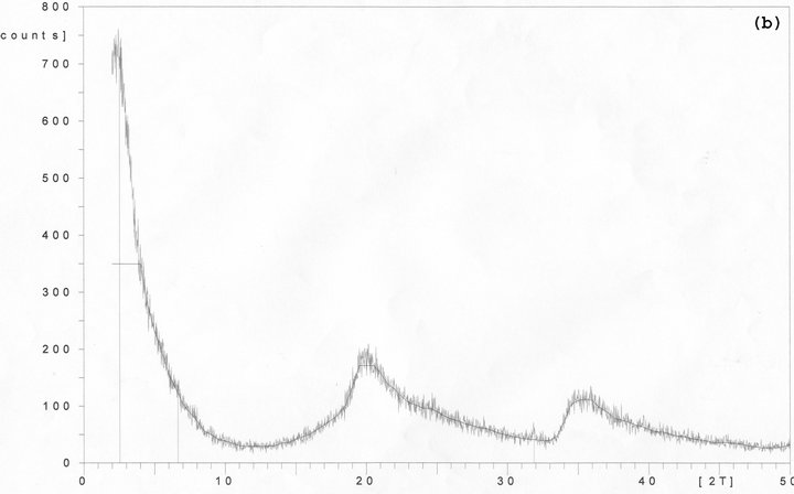
Figure 3. X-ray diffraction analysis showing the diffraction patterns that result from (a) organically modified synthetic layered silicates, (b) 3 wt% sample of processed synthetic layered silicates.
d-values for processed Cloisite®30B sample obtained from free film:
2Ө = 19 corresponding to 4.4 Å interlayer distance 2Ө = 10 corresponding to 8.6 Å interlayer distance 2Ө = 5 corresponding to 16.5 Å interlayer distance Similar to the situation for non-modified sample (Cloisite® Na+), the first three peaks of powder Cloisite®30B have disappeared and shifted to 2Ө = 19 while the main peak with the highest intensity is still at the 2Ө = 5 corresponding peak.
Further observation of Cloisite®30B behavior before and after process reveals an interesting occurrence. The overall intensity of peaks is slightly decreased. This fact is perhaps related to the use of ultrasonic deagglomerator for the dispersion process which in low viscosity systems may drive out the modifier through layered silicate layers.
Figure 3(a) shows the XRD curve of the synthetic nano layered silicate powder and Figure 3(b) shows the X-ray diffraction curve of polyurethane/3wt% synthetic nano layered silicate composite free film.
Synthetic nano layered silicate powder showed three main peaks as below:
d-values for powder:
2Ө = 35.5 corresponding to 2.5 Å interlayer distance 2Ө = 20 corresponding to 4.4 Å interlayer distance 2Ө = 3 corresponding to 30 Å interlayer distance Among three peaks detected by XRD, the 2Ө = 3 is the dominant peak while 35.5˚ and 20˚ peak’s low intensity represents a relatively good modification operation.
d-values for processed synthetic nano layered silicate:
2Ө = 19 corresponding to 4.4 Å interlayer distance;
2Ө = 8 corresponding to 11 Å interlayer distance;
2Ө ≤ 2 that indicates the interlayer distance higher than 45 Å.
Similar to all previous cases, the 2Ө = 35.5 peak disappeared. Furthermore, the 2Ө = 19 peak is significantly amplified. Although the curve pattern in Figure 3(b) predicts a dramatic rise in curve height through 2Ө values lower than 5˚ unfortunately due to uncertainly of XRD results for 2Ө values lower than 2˚, the real intensity cannot be detected.
The drying time recorder, pendulum hardness (Persoz), mandrel bending, Impact, Pull-off and gloss retention tests results are listed in Table 1. The initial gloss of all samples did not change noticeably unless for the 5 wt% sample of synthetic nano layered silicate. The initial gloss reduction of mineral clays can be interpreted as a

Table 1. Drying time recorder, pendulum hardness (Persoz), mandrel bending, impact, pull-off and gloss retention test results.
result of their bigger size in comparison to synthetic silicate used in this study. The equality of samples filled with Cloisite® Na+ and Cloisite®30B shows that the modifier plays an insignificant role regarding initial gloss and the most important parameter to be taken into account is the primary size of the layered silicate.
The gloss retention results are very interesting as we have 9% more gloss retention for synthetic layered silicate with a mere loading of 3 wt% nano filler. In case of Cloisite® Na+, gloss retention result was even worse than blank polyurethane. It implies that poor interaction between Cloisite® Na+ and polymer matrix has led to noticeable a cohesion loss throughout the coating film in this sample. The sample containing Cloisite®30B shows fairly better results in comparison to blank polyurethane whereby its gloss retention is still 5% less than synthetic sample.
The impact and Mandrel tests did not show any significant difference. All samples could pass the minimum requirements successfully. The pendulum hardness test showed significant increase in hardness 48 hrs after application in all samples where 3 wt% synthetic nano layered silicate stood on top with a distinguishable value. This indicates that the 3 wt% synthetic nano layered silicate has been able to present a higher level of uniform dispersion in comparison to the other samples. Clearly, this result is only limited to the applied thickness in this study and cannot be generalized for other coatings with different thicknesses. Nevertheless, the coating hardness increase during the first 48hrs after application can remarkably help protect the clear coat against scratch. Normally in after sale market, automobile is released less than 48 hrs after repair while a complete curing occurs 7 days after application and thus clear coat is highly sensitive to scratch in the first few days. On the other hand, this immediate coating hardness can also minimize the depth of scratches that may occur during first days.
The final pendulum hardness (after 7 days) was almost the same for all samples. The reflectance spectra of samples containing 3 wt% synthetic nano layered silicate, 3 wt% Cloisite® Na+, 3 wt% Cloisite®30B and blank polyurethane (coated on a typical white solid paint) at radiation angles of 20˚, 45˚, 75˚ and 110˚ are shown in Figure 4.


Figure 4. Reflectance curves of solid white paint coated substrate with blank clear coat, Cloisite® Na+ filled clear coat, Cloisite®30B filled clear coat and nanothix filled clear coat in four different angle (under D65 light source). All samples contain 3 wt% of filler.
In addition to the goniospectrophotometer L, a, b data, in order to find out whether the changes in reflectance spectra are detectable by human eye or not, ΔE was calculated. Pure L, a, b data of solid white paint with a blank polyurethane are listed in Table 2. For nano-filled samples, the results are listed in 4 different angles in Table 3. Colorimetric deviation averages are as below:
Synthetic Nanothix vs blank polyurethane

Table 2. Pure L, a, b data of solid white paint coated with blank PU for different light sources.

Table 3. L, a, b and ΔE data of solid white paint coated with (a) 3 wt% nanothix, (b) 3 wt% Cloisite®30B, (c) 3 wt% Cloisite® Na+.
A: 0.66 D65: 0.91 TL84: 0.84 Mineral clay Cloisite®Na+ vs blank polyurethane A: 0.87 D65: 1.2 TL84: 1.23 Mineral clay Cloisite®30B vs blank polyurethane A: 0.81 D65: 0.94 TL84: 0.94 Among the three evaluated samples, synthetic nano layered silicate showed fairly better results while organically modified nano clay (Cloisite®30B) also yielded acceptable results. Disregarding the slight shape differences between clay tactoids and an ideal sphere, the difference between Cloisite®30B and Cloisite®Na+ can be interpreted via Rayleigh equation as a result of low dispersion status which is in accordance with the XRD results. According to Rayleigh’s equation, for discrete spherical particles in an amorphous polymer matrix, the reduction in light intensity due to scattering is defined as:

where Io is the incident intensity, x is the optical path length, r is the particle radius, np is the reflective index of the particles, nm is the reflective index of the matrixV is the volume fraction of particles and λ is the wavelength of light.
Scratch resistance test results showed an obvious improvement in scratch resistance of nano-filled clear coats in presence of nano filler. Figure 5 shows the microscopic images of automatic scratch test for blank polyurethane, the 3 wt% synthetic nano layered silicate and 3 wt% Cloisite®30B nano clay samples. In all cases, loaded weight is 2000 grams. Figure 6 shows images of an incision made over polymer films.
Figure 7 shows microscopic images of different samples after 70 double rubs of abrasive which confirms the automatic scratch resistance test results. Some gloss retention results obtained from these samples are listed in Table 1. In addition, samples did not show noticeable difference in case of the chipping test at the applied thickness.
In order to trace the adhesion behavior of coatings, digital Pull-off test was employed. Results are listed in Table 1. In comparison with control sample (blank polyurethane), the 1 wt% nanothix filled sample and 3 wt% Cloisite®30B filled polyurethane showed adhesion improvement. There was also a slight increase in adhesion for 3 wt% nanothix filled sample. Considering the operation method of pull-off, this adhesion increase is mainly related to the polymer film cohesion strength resulting from polymer/nano layers interaction. Comparing to blank polyurethane, the 5 wt% nano-filled sample showed significant decrease in adhesion equal to 30%.

Figure 5. Microscopic images of (a) blank clear coat, (b) 3 wt% nanothix filled polyurethane, (c) 3 wt% nano Cloisite®30B filled polyurethane. In all cases weight load is 2000gr.

Figure 6. Microscopic images of (a) blank clear coat, (b) 3 wt% Cloisite®30B filled polyurethane and (c) 3 wt% nanothix filled polyurethane.

Figure 7. Microscopic images of (a) blank Polyurethane (b) 3 wt% nanothix filled polyurethane, (c) 3 wt% nano Cloisite®30B filled polyurethane, (d) 3 wt% nano Cloisite® Na+ filled polyurethane, (e) 1 wt% nanothix filled polyurethane and (f) 1 wt% nano Cloisite®30B filled polyurethane after 70 double rubs.
4. Conclusions
Three different samples containing mineral and synthetic nano layered silicate were prepared and compared with a blank polyurethane clear coat. Among tested samples, 3 wt% sample of synthetic nano layered silicate yielded better results in most cases.
Scratch test showed an improvement after 7 days while a significant hardness increase was observed during merely 48 hours after coating application. This makes coating less sensitive to scratches that may occur during the first days after repair. Furthermore, the optical property of samples slightly changed where synthetic layered silicate contained sample presented least deviation. L, a, b and ΔE results showed that the deviation of the aforementioned sample is not detectable by the naked eye. Gloss retention results showed a significant improvement in comparison to blank polyurethane while initial gloss and dry to touch property of samples did not change noticeably. Adhesion presented different behavior in each case. It decreased in case of non-modified clay and 5 wt% of synthetic layered silicate while increased in case of modified clay and 1 wt% synthetic layered silicate. Adhesion did not alter noticeably for the 3 wt% synthetic sample. Other common requirements of an automotive clear coat such as bending resistance (flexibility) and impact resistance were not affected by nano filler presence at the applied thickness.
5. Acknowledgements
The authors gratefully acknowledge the support of Khosh Paint & Resin Co. Ltd.
REFERENCES
- B. V. Gregorovich, K. Adamsons and L. Lin, “Scratch and Mar and Other Mechanical Properties as a Function of Chemical Structure for Automotive Refinish Coatings,” Progress in Organic Coatings, Vol. 43, No. 1-3, 2001, pp. 175-187. doi:10.1016/S0300-9440(01)00187-4
- L. Lin, G. S. Blackman and R. R. Matheson, “Quantitative Characterization of Scratch and Mar Behavior of Polymer Coatings,” Materials Science and Engineering, Vol. 317, No. 1-2, 2001, pp. 163-170. doi:10.1016/S0921-5093(01)01159-5
- A. Krupicka, M. Johansson and A. Hult, “Use and Interpretation of Scratch Tests on Ductile Polymer Coatings,” Progress in Organic Coatings, Vol. 46, No. 1, 2003, pp. 32-48. doi:10.1016/S0300-9440(02)00184-4
- M. Groenewolt, “Highly Scratch Resistant Coatings for Automotive Applications,” Progress in Organic Coatings, Vol. 61, No. 2-4, 2008, pp. 106-109. doi:10.1016/j.porgcoat.2007.07.036
- E. Barna, B. Bommer, J. Kursteiner, A. Vital, O. V. Trzebiatowski, W. Koch, B. Schmid and T. Graule, “Innovative, Scratch Proof Nanocomposites for Clear Coatings,” Composites Part A, Vol. 36, No. 4, 2005, pp. 473-480. doi:10.1016/j.compositesa.2004.10.014
- Y. Kojima, A. Usuki, M. Kawasumi, A. Okada, Y. Fukushima, T. Kurauchi and O. Kamigaito, “Mechanical Properties of Nylon 6-Clay Hybrid,” Journal of Materials Research, Vol. 8, No. 5, 1993, pp. 1185-1189. doi:10.1557/JMR.1993.1185
- A. Okada and A. Usuki, “The Chemistry of Polymer-Clay Hybrids,” Materials Science and Engineering: C, Vol. 3, No. 2, 1995, pp. 109-115. doi:10.1016/0928-4931(95)00110-7
- P. Messersmith and E. P. Giannelis, “Synthesis and Characterization of Layered Silicate-Epoxy Nanocomposites,” Chemistry of Materials, Vol. 6, No. 10, 1994, pp. 1719-1725. doi:10.1021/cm00046a026
- S. Manne and I. A. Aksay, “Thin Films and Nanolaminates Incorporating Organic/Inorganic Interfaces,” Current Opinion in Solid State & Materials Science, Vol. 2, No. 3, 1997, pp. 358-364. doi:10.1016/S1359-0286(97)80128-3
- T, Lan and T. J. Pinnavaia, “Clay-Reinforced Epoxy Nanocomposites,” Chemistry of Materials, Vol. 6, No. 12, 1994, pp. 2216-2219. doi:10.1021/cm00048a006
- H. Shi, T. Lan and T. J. Pinnavaia, “Interfacial Effects on the Reinforcement Properties of Polymer-Organoclay Nanocomposites,” Chemistry of Materials, Vol. 8, No. 8, 1996, pp. 1584-1587. doi:10.1021/cm960227m
- B. Ahmadi, S. M. Kassiriha, K. Khodabakhshi and E. R. Mafi, “Effect of Nano Layered Silicates on Automotive Polyurethane Refinish Clear Coat,” Progress in Organic Coatings, Vol. 60, No. 2, 2007, pp. 99-104. doi:10.1016/j.porgcoat.2007.07.008
- J. W. Gilman, “Flammability and Thermal Stability Studies of Polymer Layered-Silicate (Clay) Nanocomposites,” Applied Clay Science, Vol. 15, No. 1-2, 1999, pp. 31-49. doi:10.1016/S0169-1317(99)00019-8
- F. Dietsche and R. Mulhaupt, “Thermal Properties and Flammability of Acrylic Nanocomposites Based Upon Organophilic Layered,” Polymer Bulletin, Vol. 43, No. , 1999, pp. 395-402. doi:10.1007/s002890050627
- D. Porter, E. Metcalfe and M. J. K. Thomas, “Nanocomposite Fire Retardants—A Review,” Fire Mater, Vol. 24, No. 1, 2000, pp. 45-52. doi:10.1002/(SICI)1099-1018(200001/02)24:1<45::AID-FAM719>3.0.CO;2-S
- J. W. Gilman, C. L. Jackson, A. B. Morgan, R. Harris, E. Manias, E. P. Giannelis, et al., “Flammability Properties of Polymer−Layered-Silicate Nanocomposites. Polypropylene and Polystyrene Nanocomposites,” Chemistry of Materials, Vol. 12, No. 7, 2000, pp. 1866-1873. doi:10.1021/cm0001760
- K. Yano, Y. Kojima, A. Usuki, A. Okada, T. Kurauchi and O. Kamigaito, “Synthesis and Properties of Polyimide-Clay Hybrid,” Journal of Polymer Science Part A: Polymer Chemistry, Vol. 31, No. 10, 1993, pp. 2493- 2498. doi:10.1002/pola.1993.080311009
- T. Lan, P. D. Kaviratna and T. J. Pinnavaia, “On the Nature of Polyimide-Clay Hybrid Composites,” Chemistry of Materials, Vol. 6, No. 5, 1994, pp. 573-575. doi:10.1021/cm00041a002
- P. B. Messersmith and E. P. Giannelis, “Synthesis and Barrier Properties Of Poly(
 -caprolactone)-Layered Silicate Nanocomposites,” Journal of Polymer Science Part A: Polymer Chemistry, Vol. 33, No. 7, 1995, pp. 1047- 1057. doi:10.1002/pola.1995.080330707
 - S. D. Burnside and E. P. Giannelis, “Synthesis and Properties of New Poly(dimethylsiloxane) Nanocomposites,” Chemistry of Materials, Vol. 7, No. 9, 1995, pp. 1597- 1600. doi:10.1021/cm00057a001
- M. S. Cho, H. J. Choi and K. To, “Effect of Ionic Pendent Groups on a Polyaniline-Based Electrorheological Fluid,” Macromolecular Rapid Communications, Vol. 19, No. 6, 1998, pp. 271-273. doi:10.1002/(SICI)1521-3927(19980601)19:6<271::AID-MARC271>3.0.CO;2-O
- S. G. Kim, J. W. Kim, M. S. Cho, H. J. Choi and M. S. Jhon, “Viscoelastic Characterization of Semiconducting Dodecylbenzenesulfonic Acid Doped Polyaniline Electrorheological Suspensions,” Journal of Applied Polymer Science, Vol. 79, No. 1, 2000, pp. 108-114. doi:10.1002/1097-4628(20010103)79:1<108::AID-APP130>3.0.CO;2-8
- J. M. Yeh, S. J. Liou, C. Y. Lin, C. Y. Cheng, Y. W. Chang and K. R. Lee, “Anticorrosively Enhanced PMMAClay Nanocomposite Materials with Quaternary Alkylphosphonium Salt as an Intercalating Agent,” Chemistry of Materials, Vol. 14, No. 1, 2002, pp. 154-161. doi:10.1021/cm010337f
- J. M. Yeh, S. J. Liou, M. C. Lai, Y. W. Chang, C. Y. Huang, C. P. Chen, et al., “Comparative Studies of the Properties of Poly(methyl methacrylate)-Clay Nanocomposite Materials Prepared by in Situ Emulsion Polymerization and Solution Dispersion,” Journal of Applied Polymer Science, Vol. 94, No. 5, 2004, pp. 1936-1946. doi:10.1002/app.21095
- J. M. Yeh, S. J. Liou, H. J. Lu and H. Y. Huang, “Enhancement of Corrosion Protection Effect of Poly (Styrene-Co-Acrylonitrile) by the Incorporation of Nanolayers of Montmorillonite Clay into Copolymer Matrix,” Journal of Applied Polymer Science, Vol. 92, No. 4, 2004, pp. 2269-2277. doi:10.1002/app.20232
- J. M. Yeh, S. J. Liou, C. G. Lin, Y. P. Chang, Y. H. Yu and C. F. Cheng, “Effective Enhancement of Anticorrosive Properties of Polystyrene by Polystyrene-Clay Nanocomposite Materials,” Journal of Applied Polymer Science, Vol. 92, No. 3, 2004, pp. 1970-1976. doi:10.1002/app.13436
- J. M. Yeh, C. L. Chen, Y. C. Chen, C. Y. Ma, H. Y. Huang, Y. H. Yu, “Enhanced Corrosion Prevention Effect of Polysulfone-Clay Nanocomposite Materials Prepared by Solution Dispersion,” Journal of Applied Polymer Science, Vol. Vol. 92, No. 1, 2004, pp. 631-637. doi:10.1002/app.13435
- J. M. Yeh, H. Y. Huang, C. L. Chen, W. F. Su and Y. H. Yu “Siloxane-Modified Epoxy Resin-Clay Nanocomposite Coatings with Advanced Anticorrosive Properties Prepared by a Solution Dispersion Approach,” Surface and Coatings Technology, Vol. 200, No. 8, 2006, pp. 2753-2763. doi:10.1016/j.surfcoat.2004.11.008
- Y. H. Yu, J. M. Yeh, S. J. Liou and Y. P. Chang, “Organo-Soluble Polyimide (TBAPP-OPDA)/Clay Nanocomposite Materials with Advanced Anticorrosive Properties Prepared from Solution Dispersion Technique,” Acta Materialia, Vol. 52, No. 2, 2004, pp. 475-486. doi:10.1016/j.actamat.2003.09.031
- J. M. Yeh, C. F. Hsieh, J. H. Jaw, T. H. Kuo, H. Y. Huang, C. L. Lin, et al., “Organo-Soluble Polyimde (ODA-BSAA)/Montmorillonite Nanocomposite Materials Prepared by Solution Dispersion Technique,” Journal of Applied Polymer Science, Vol. 95, No. 5, 2005, pp. 1082- 1090. doi:10.1002/app.21317
- Y. H. Yu, J. M. Yeh, S. J. Liou, C. L. Chen, D. J. Liaw and H. Y. Lu, “Preparation and Properties of PolyimideClay Nanocomposite Materials for Anticorrosion Application,” Journal of Applied Polymer Science, Vol. 92, No. 6, 2004, pp. 3573-3582.
- J. M. Yeh, C. L. Chen, T. H. Kuo, W. F. Su, H. Y. Huang, D. J. Liaw, et al., “Preparation and Properties of (BATBODPA) Polyimide-Clay Nanocomposite Materials,” Journal of Applied Polymer Science, Vol. 92, No. 2, 2004, pp. 1072-1079. doi:10.1002/app.13437
- J. M. Yeh, S. J. Liou, C. Y. Lai, P. C. Wu, T. Y. Tsai, “Enhancement of Corrosion Protection Effect in Polyaniline via the Formation of Polyaniline-Clay Nanocomposite Materials,” Chemistry of Materials, Vol. 13, No. 3, 2001, pp. 1131-1136. doi:10.1021/cm000938r
- J. M. Yeh, C. L. Chen, Y. C. Chen, C. Y. Ma, K. R. Lee, Y. Wei, et al., “Enhancement of Corrosion Protection Effect of Poly(o-ethoxyaniline) via the Formation of Poly(oethoxyaniline)-Clay Nanocomposite Materials,” Polymer, Vol. 43, No. 9, 2002, pp. 2729-2736. doi:10.1016/S0032-3861(02)00005-8
- K. C. Chang, M. C. Lai, C. W. Peng, Y. T. Chen, J. M. Yeh, C. L. Lin, et al., “Comparative Studies on the Corrosion Protection Effect of DBSA-Doped Polyaniline Prepared from in Situ Emulsion Polymerization in the Presence of Hydrophilic Na+-MMT and Organophilic OrganoMMT Clay Platelets,” Electrochimica Acta, Vol. 51, No. 26, 2006, pp. 5645-5653. doi:10.1016/j.electacta.2006.02.039
- Y. H. Yu, C. C. Jen, H. Y. Huang, P. C. Wu, C. C. Huang and J. M. Yeh, “Preparation and Properties of Heterocyclically Conjugated Poly(3-hexylthiophene)-Clay Nanocomposite Materials,” Journal of Applied Polymer Science, Vol. 91, No. 6, 2004, pp. 3438-3446. doi:10.1002/app.13457
- J. M. Yeh, C. P. Chin and S. Chang, “Enhanced Corrosion Protection Coatings Prepared from Soluble Electronically Conductive Polypyrrole-Clay Nanocomposite Materials,” Journal of Applied Polymer Science, Vol. 88, No. 14, 2003, pp. 3264-3272. doi:10.1002/app.12146
- J. M. Yeh and C. P. Chin, “Structure and Properties of Poly(o-methoxyaniline)-Clay Nanocomposite Materials,” Journal of Applied Polymer Science, Vol. 88, No. 4, 2003, pp. 1072-1080.
- R. E. Grim, “Clay Mineralogy,” second ed., New York: McGraw Hill, 1968, p.362.
- R. Tantatherdtam, “Reinforcement of Natural Rubber Latex by Nanosize Montmorillonite Clay,” Ph.D. Thesis, Department of Materials Science and Engineering, University Park, 2003.
- E. P. Giannelis, “Polymer Layered Silicate NanocompoSites,” Advanced Materials, Vol. 8, No. 1, 1996, pp. 29- 35. doi:10.1002/app.12146
- P. C. LeBaron, Z. Wang and T. J. Pinnavaia, “PolymerLayered Silicate Nanocomposites: An Overview,” Applied Clay Science, Vol. 15, No. 1-2, 1999, pp. 11-29. doi:10.1016/S0169-1317(99)00017-4
- Y. Fukushima and S. Inagaki, “Synthesis of an Intercalated Compound of Montmorillonite and 6-Polyamide,” Journal of Inclusion Phenomena and Macrocyclic Chemistry, Vol. 5, No. 4, 1987, pp. 473-482. doi:10.1007/BF00664105
- R. S. Berns, “Billmeyer and Saltzman’s Principles of Color Technology,” Third Edition, Wiley, New York, 2000, p. 127.