Journal of Flow Control, Measurement & Visualization
Vol. 1 No. 3 (2013) , Article ID: 37592 , 9 pages DOI:10.4236/jfcmv.2013.13010
Flip-Flop Flow Control inside Streamwise Diverging Diamond-Shaped Cylinder Bundles with Concavities
1Department of Mechanical System Engineering, Kumamoto University, Kumamoto, Japan
2Department of Architecture and Civil Engineering, Fukuyama University, Fukuyama, Japan
Email: torii@mech.kumamoto-u.ac.jp, s-umeda@fucc.fukuyama-u.ac.jp
Copyright © 2013 Shuichi Torii, Shizaburo Umeda. This is an open access article distributed under the Creative Commons Attribution License, which permits unrestricted use, distribution, and reproduction in any medium, provided the original work is properly cited.
Received April 3, 2013; revised June 24, 2013; accepted August 12, 2013
Keywords: Flip-Flop Flow; Streamwise Diverging Diamond-Shaped Cylinder Bundle; PIV Measurement; Concavity
ABSTRACT
The flow visualization work with the aid of PIV and Piezometer deals with flip-flop flow around diamond-shaped cylinder bundle revised with concavities on both bundle walls. It is disclosed that 1) the concavity constructed on both side-walls of a diamond cylinder induces a substantial change in the flow patterns in the exit jet-stream field and jetstream dispersion, 2) pressure characteristics are quantitatively measured in a diverging-flow region in diamond cylinder bundles with concavity and in its downstream region, and 3) flip-flop flow occurs in the flow passages and its occurrence condition is obtained.
1. Introduction
During the decade of 1970’s, motivated by the development of a flip-flop nozzle by Viets [1] to produce the switching action of jet streams, the application research of fluidics units became active. The flip-flop flow deals with a single jet flow as objective but has a circuit route for injection control in certain cases. In contrast, the flip-flop flow in diamond-shaped cylinder bundles developed by Umeda et al. [2] was induced by the self-excited oscillation of vortices which utilized variation in the cross-section width in the flow passages. Hence, its oscillating frequency was different and its inclination required no control other than the Coanda effect which corresponded to the sticking phenomenon of flow streak-lines on the cylinder walls. Furthermore, multiple jet streams could be simultaneously controlled. Its fluids engineering applications are demonstrated in granting of the fundamental patents inside planting tanks [3,4] and are expected to manifest a strong influence in the future.
In addition to the concise reviews of both a continuous intersecting flow of the converging and diverging flow of the main stream and a flip-flop flow behind diamond cylinder bundle, the present study is performed on the flow characteristics around diamond-shaped cylinder bundle revised with concavities on both bundle walls.
1.1. Intersecting Flow
Figure 1 is a schematic of flows in an intersecting duct. Here, “left” or “right” refers to its respective position in the flow direction. The “inner wall” refers to those intersecting channel walls which are confined within the central longitudinal lines, while the “outer wall” corresponds to the left and right walls outside the central longitudinal lines. Flows from both the left and right upstream of the intersecting channels collide in the converging-flow region of the intersection section. As a result, the b-b’ cross section where the cross-sectional area is narrowest is

Figure 1. A schematic of flows in intersecting ducts.
characterized by a large pressure gradient [5] with higher pressure in the central portion and negative pressure on both ends. This phenomenon is seen to occur as the pushin pressure at the air-intake entrance (compressor) of jet aircrafts and is known as ramming or ramming effect. In the diverging-flow region, due to the contraction of converging-flow streams, it creates an energy source point [6] on the a-a’ cross section in the intersection section where the flow speed becomes maximum while the pressure is minimum. Accompanying flow separation from the left and right inner walls is the generation of vortices ([7], called separation vortices). Simultaneously, von Karman vortex-street oscillations take place as the Reynolds number (Re) is increased. The Coanda effect [8], adherence of flow streak-lines on a surface, acts near the outer walls of the intersecting channels in the intersection section. In addition, a shear layer is formed like a wall on the central longitudinal line (a-a’) in the intersection section which is caused by the collision of flows. This shear layer undergoes a random fluctuation [9] near the branching point (a’). On the other hand, through the sealing, socalled “Close” of one upstream channel in Figure 1, suction phenomenon induced by a rotating vortex in the intersection section [8] can be produced to significantly enhance the downstream efflux flow rate. All these phenomena occur through utilization of extra channels attached in front of and from behind the intersection section.
1.2. Flip-Flop Flow
Umeda et al. [10] studied the cross-sectional view of a flow network with a single intersection and a flow system consisting of mutually intersecting flow passages inside a plate or an assembly of plates. The fundamental study on a flip-flop flow of a single jet stream was reported, as seen Figure 2 [10]. Here, the number, for each cylinder, is indicated in Figure 2. The production of wake is constructed around the diamond cylinders, i.e., No. 3 and No. 4 and the corresponding trace of wake is shown as the dash line. One observes that the location of wake around No. 4 of the cylinder is opposite as shown in Figures 2(b) and (d) and the similar trend around No. 3 of the cylinder appears in Figures 2(c) and (e). Consequently the direction of jet-stream is changed between Figures 2(c) and (d). In other words, such flow phenomenon, i.e., flip-flop flow is attributed to the motion of the wake in the channel.
Umeda et al. [11] studied the flow characteristics of flip-flop flow in the diverging-flow region in the flow passages of a six-row diamond-shaped cylinder bundle (Figure 3). They reported that 1) at the third row, the magnitude of power spectra reaches maximum near the “energy source point”, but subsequently diminishes to the minimum value at the apex of the succeeding cylinder where micro vortices alternately shedding on each of the

Figure 2. Changes in pattern of flow streaklines and separation vortices during flow through the diamond geometry (dt ≒ 0.24 sec.).
Figure 3. Schematic diagram of convergingand divergingflow region inside a diamond-shaped cylinder bundles.
downstream surface, 2) the flow exhibits the characteristics of a jet tone and 3) the occurrence of conjunct separation vortex appears in the separation zone of the xshaped intersecting flow. In particular, Umeda et al. [2] and Umeda and Yang [12] discovered self-excited multiple jet-stream groups from diamond-shaped cylinder bundles. It was disclosed that these flow fields construct multiple jet streams of equal flow rates at the exit which are symmetrical with the central longitudinal line as the axis. When a flip-flop flow is generated from a diamond-shaped cylinder bundle, the von Karman vortices which are generated in both leftand right-rear-flow regions behind the cylinders undergo fluctuations. Umeda et al. [2] found the generation mechanism of these oscillations through identifying reciprocating migration of the conjunct separation vortex pair and the Coanda effect of the flow streaklines as the necessary factors and the x-shaped intersecting flow of the main stream as the auxiliary factors. Furthermore, Umeda et al. [13] studied flip-flop flow oscillation from a diamond-shaped cylinder bundle with concavity on bundle walls. They disclosed that the presence of concavity results in a remarkable change in the jet-stream from the diamond-shaped cylinder bundle in higher turbulence levels and dispersion of individual jet-streams with respect to those without-concavities [13].
In industrial applications of the exit oscillation jet streams, the diamond-shaped cylinder bundles provide an exit jet stream flow field with multiple equal flow-rate jetstream group having self-excited oscillations and can be applied to fluids engineering machinery for mixing, stirring, diffusion, heat transfer and cleaning operations. It should be noticed that the corresponding flow fields and various devices require the improvement of further functions as advanced devices. That is, 1) although flip-flop flow is observed in the exit jet streams from the flow passages, its direction indicated oscillations are within 30˚ whose wideness is somewhat narrow and 2) a diamondshaped cylinder bundle which consists of multiple rows of diamond-shaped cylinders with 30˚ apex angle in staggered arrangement, amplifies the pressure drop in the channel. In order to develop the application device, furthermore development and pressure characteristics in the channel may be requested.
1.3. Streamwise Diverging Diamond-Shaped Cylinder Bundle
As the self-excited multiple jet-stream groups from diamond-shaped cylinder bundles which constructs the uniform flow from multi-injection flow, authors [14-16] reported injection-flow characteristics in the revised channel in the presence of a diamond-shaped cylinder bundle with the fourth row bundles having an apex angle of 30˚ and the following row bundles of diamond-shaped cylinders having an apex angle of 60˚. They disclosed that suction effect is induced by the rotation of the vortex in the concavities constructed on both sidewalls inside the diamond-shaped cylinder bundle. In contrast, substantial attenuation in pressure drop does not cause at the location of the concavities because it is constructed on both sidewalls. Based on the flow result, the diamond-shaped cylinder bundles were modified. In other words, the circular cavities are constructed on fifth and sixth row bundles and the minimum distance between twin diamondcylinders were extended from w1 to w2, as seen in Figure 4. Thus two phenomena are expected as 1) the flow and pressure sprit region is affected by the flow separation and the vortices due to presence of the cavities on the bundles and 2) the pressure drop is attenuated due to the wide flow area in the downstream area of fifth row of diamond bundles. This pressure attenuation is similar to that due to the lens effect of the wind in the wind power generator [17].
The present study is performed on the flow characteristics around diamond-shaped cylinder bundle revised with concavities on both bundle walls. Here, the revised channel with a diamond-shaped cylinder bundle is consisted of the fourth row bundles having an apex angle of 30˚, diamond-shaped cylinders with an increase in 10˚ interval apex in the downstream direction, and eighth row bundle of diamond-shaped cylinders with having an apex angle of 60˚ [16]. For comparison, the other two different channels are employed, that is the circular cavities are constructed on fifth and sixth row bundles and the minimum distance between twin-diamond-cylinders were gradually extended in the downstream direction. Consideration is given to the pressure and flow injection flow characteristics.
2. Experimental Methods
2.1. Experimental Apparatus
Experimental measurements are performed on flows in the passages and exiting jet streams from streamwise diverging diamond-shaped cylinder bundles with and without concavity. Both water and air are employed as test fluids. Figures 5(a) and (b) display an entire schematic diagram of the experimental setup of a diamond-shaped cylinder bundle, when air is used as the test fluid. The experimental setup consists of blower, calming duct, test section, i.e., cylinder bundle and measuring region with the aid of PIV. Note that if water is employed as the test fluid, an upstream head tank with head of Hu to supply water, is used in place of blower and a water reservoir is attached downstream to collect the water for recirculation using a pump (not shown). A rectified-flow passage is needed upstream of the diamond-shaped cylinder bundle to generate flip-flop flow. Therefore, a flow-calming section is installed to supply air from a blower, as illustrated in Figure 5.
In the present study, three different channels are em-

Figure 4. Schematic diagram of convergingand divergingflow region around the 5th and 6th rows.
Figure 5. Schematic diagram of the experimental setup.
ployed in which an apex of a diamond-shaped cylinder bundle is gradually increased in the downstream direction. The top view of the channel is depicted in Figure 6 in which the circular concavity is constructed on both side-walls of the cylinder at the fifth and sixth row bundles of diamond-shaped cylinders and the corresponding cavity diameter is 2 mm. Here the channel including the multiple rows of diamond-shaped cylinders and the final row of cylinder with 60˚ is referred to as “Type D60cd”.
As the other type, Type D60Wcd is employed in which the bundle of “Type D60cd” is used and at seventh and eighth row the channel width between twin-diamond cylinders is changed from 5 mm to 7 mm, as seen in Figure 7. For comparison, the channel with a diamond-shaped cylinder bundle which is consisted of the fourth row bundles having an apex angle of 30˚, diamond-shaped cylinders with an increase in 10˚ interval apex in the downstream direction, and eighth row bundle of diamondshaped cylinders with having an apex angle of 60˚ [16], is employed as mentioned in the previous section. The corresponding channel configuration is the same as that in Figure 6 in the absence of the circular concavities. This is named as “Type D60n” [16].
As for three different diamond-shaped cylinder bundles, since the substantial narrow flow cross-section easily causes the flip-flop flow, the square duct shape in which the channel height d, short axis width of diamondshaped cylinder and narrowest flow cross-section width are the same as 5 mm, is employed.
Figure 6. Schematic of the streamwise diverging diamondshaped cylinder bundle (Type D60cd).

Figure 7. An arrangement diagram around the 7th row in the streamwise diverging diamond-shaped cylinder bundle (Type D60Wcd).
2.2. Piezometer Measurement in Cylinder Bundles
In order to measure the pressure drop in three different channels employed here, the head Hu of the upstream head tank is varied to change flow rates through the test section, and Pu/ρg and Pd/ρg at the first and seventh row of diamond-shaped cylinders is estimated, respectively. The corresponding locations are shown in Figure 6 as the “ ” which is the narrowest channel cross-section at the first and seventh row of diamond-shaped cylinders, respectively. The inlet flow rate is varied based on the Reynolds number Re, which is defined using the exit flow rate divided by the flow passage cross-sectional area as the characteristic flow velocity and the passage thickness d of 5 mm as the characteristic length.
2.3. Flow Measurement of Air Jet Stream
Flow measurements were performed in the measuring region shown in Figure 5(a). In case of supplying air from a blower, a smoke generator was installed at the suction. Here the co-ordinate system is provided identifying the location in the measuring region, as shown in Figure 5. The origin of the co-ordinate system is set at the center of the exit from the diamond-shaped cylinder bundle, measuring the flow direction by the x-axis, the lateral direction by the y-axis, and the vertical direction by the z-axis.
Using CLIMOMASTER (KANOMAX Co.), the air flow rate is measured and the Reynolds number is calculated in which the maximum time-averaged velocity, Umax, is obtained at x = 5 mm, z = 0, y = 5mm from the channel flow exit and the channel height, d, is used. The flow velocity distribution are carried out along y-axis at x = 50 mm.
As the other flow measurement method, PIV (LaVision Co.)is employed. In general, the advanced PIV methods are the high resolution, 3-dimentional flow filed, time-resolution and stereo measurements (for reference, [18]). Here two-dimensional PIV measurements are performed on the horizontal x-y plane, x ranging from 10 to 110 mm and y = −30 - 30 mm on the horizontal central cross section at z = 0.
In case of supplying air from a blower, a smoke generator is installed at the suction port to simultaneously supply a tracer for the PIV. Results of the PIV measurements are recorded using a CCD camera with the sampling frequency of 15 Hz, the pulse interval of 25 μs, and the pixel number of 1340 by 1040. Vector images of 500 frames in which a vector is estimated by 32 × 32 pixel, are obtained.
3. Experimental Results and Discussion
3.1. Results of Pressure Measurement
The flow rate (equivalently, the flow velocity) inside the channel is varied by adjusting the head, Hu, of the tank. Using the channels employed here and the corresponding Hu, Piezometric head measurement was carried out. This measurement estimates the pressure drop in three different channels used in the present study. In order to study the effect of flow rate, i.e., Hu on the pressure drop of the three different channels, the following two pressure coefficients are evaluated as:
 (1)
(1)
 (2)
(2)
Here, the averaged velocity, U, over the cross-section of the channel is estimated based on the flow rate measurement and the flow cross-section of the channel and Pu and Pd are obtained at the location of Piezometric head measurement, as shown in Figure 6. g is gravity and U is used as the characteristic velocity of the Reynolds number, Re.
Figure 8 depicts the variation of pressure loss coefficient versus the Reynolds number. One observes that the pressure coefficients for Type D60cd and Type D60n are decreased with an increase in Reynolds number. Note that for TypeD60cd, the pressure drop in the low Reynolds number region, i.e., near Re = 5000 becomes larger due to the irregular presence of a flip-flop flow. On the contrary, the corresponding values, i.e., Cp1 and Cp2 are lower, are not affected by the Reynolds number and is almost constant over the wide range of Re. It is postulated that the flow characteristics for Type D60Wcd are caused by the pressure reduction in the concavity and by an enhancement of the channel width in the downstream direction, as seen in Figure 7. In other words, the suction effect in the concavity [13] causes the flow fluctuation and changes in the channel width, resulting in enhancement of flow smoothness. As for Piezometric head measurement, the uncertainty for Cp is estimated to be ±2.5%, because of the presence of flip-flop flow due to the wake oscillation in the channel and the scale resolution, i.e., 1 mm by the naked eye.
3.2. Flow Measurement and Visualization of Air Jet Stream
The blower installed at the upstream side was operated by the inverter controller whose frequency can be changed between 10 Hz and 30 Hz. Air jet-stream velocity exiting from diamond shaped-cylinder bundles with the concavity varied substantially depending on location and flip-flop flow oscillations occur as seen in the case of water jet-stream.
3.2.1. Flow Measurement of Jet Stream
The jet-stream velocity fields in the vicinity of the channel exit were measured with the aid of the anemometer.

Figure 8. Changes of Cp versus Re.
One observes that the flow characteristics of flip-flop flow appear in the diverging-flow region and at exit of the flow passages and are almost symmetry along the axes of the center of the longitudinal direction. Here, the flow distribution of the cross-section of the channel is measured at y = 0, 20, 40 and 60 mm along the y-axis at x = 50 mm. The corresponding four locations are ranged from z = 30 mm to z = −30 mm. Among these measurement results, the velocity distribution of maximum injection velocity is summarized in Figure 9 for three different channels. Here the velocity is normalized by the maximum velocity, Umax as mentioned previously.
One observes that the maximum value of streamwise velocity appears over the cross-section at z = 0 for all types, but there is the effect of measurement location, i.e., z = +/−10 mm on the flow velocity. For Type D60n and Type D60cd, the velocity distribution in the y-direction is increased with an increase in y-location. In contrast, for
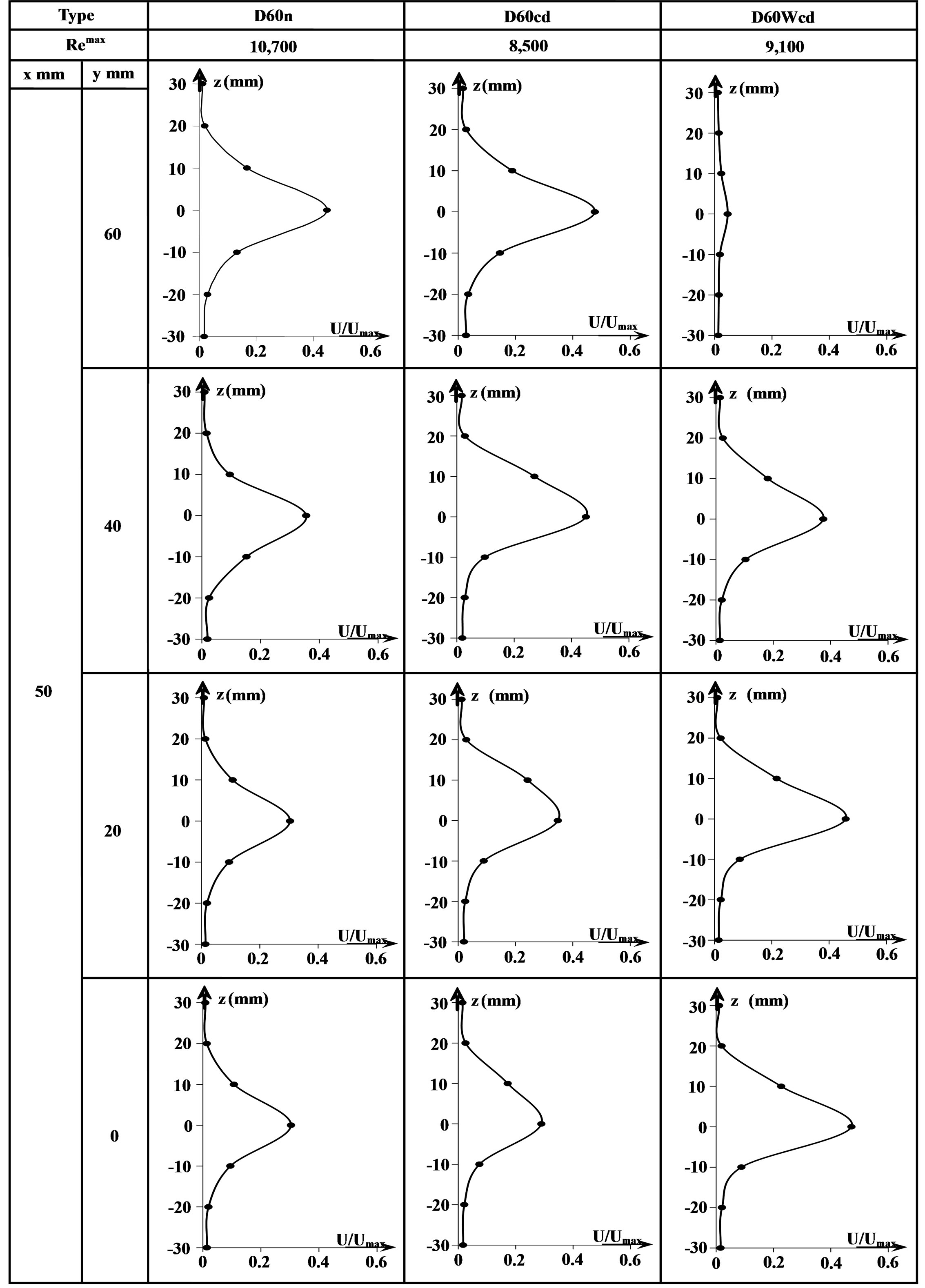
Figure 9. Velocity distributions of jet streams on a vertical section from streamwise diverging diamond-shaped cylinder bundles.
Type D60Wcd, the corresponding maximum value appears at y = 0 mm and y-direction velocity is attenuated along the y-direction and yields the substantial reduction at y = 60 mm.
Throughout all types shown here, it is found that 1) the flip-flop flow induced from the diamond-shaped cylinder bundles occurs, in particular, the maximum velocity, for Type D60cd, takes place near y = 60 mm and the wider flow oscillation causes and 2) the flow characteristics for Type D60n is similar to that for Type D60cd, but the absolute values are slightly different between both types. On the contrary, for Type D60Wcd, larger flow velocity area yields in the vicinity of the central part in the horizontal direction, the corresponding horizontal flow oscillation is lower than the other two types, and the substantial deterioration of the flow velocity causes near y = 60 mm. Based on the results, the three dimensional flow is found to cause for all types, as shown here.
3.2.2. Visualization of Jet Stream
Using the velocity visualization measurement with the aid of PIV, the iso-velocity distribution and the mean values of the jet-stream velocity-variation rate, dV/dy, are illustrated in Figure 10 for different channels with the diamond-shaped cylinder bundle. Here, V implies the mean y-direction velocity over the cross-section of channel. It is observed that the profiles of the iso-velocity and iso-dV/dy are almost symmetry along the y-axis and the flip-flop flow induced occurs as expected. The similar flow distributions for iso-velocity are shown for Type
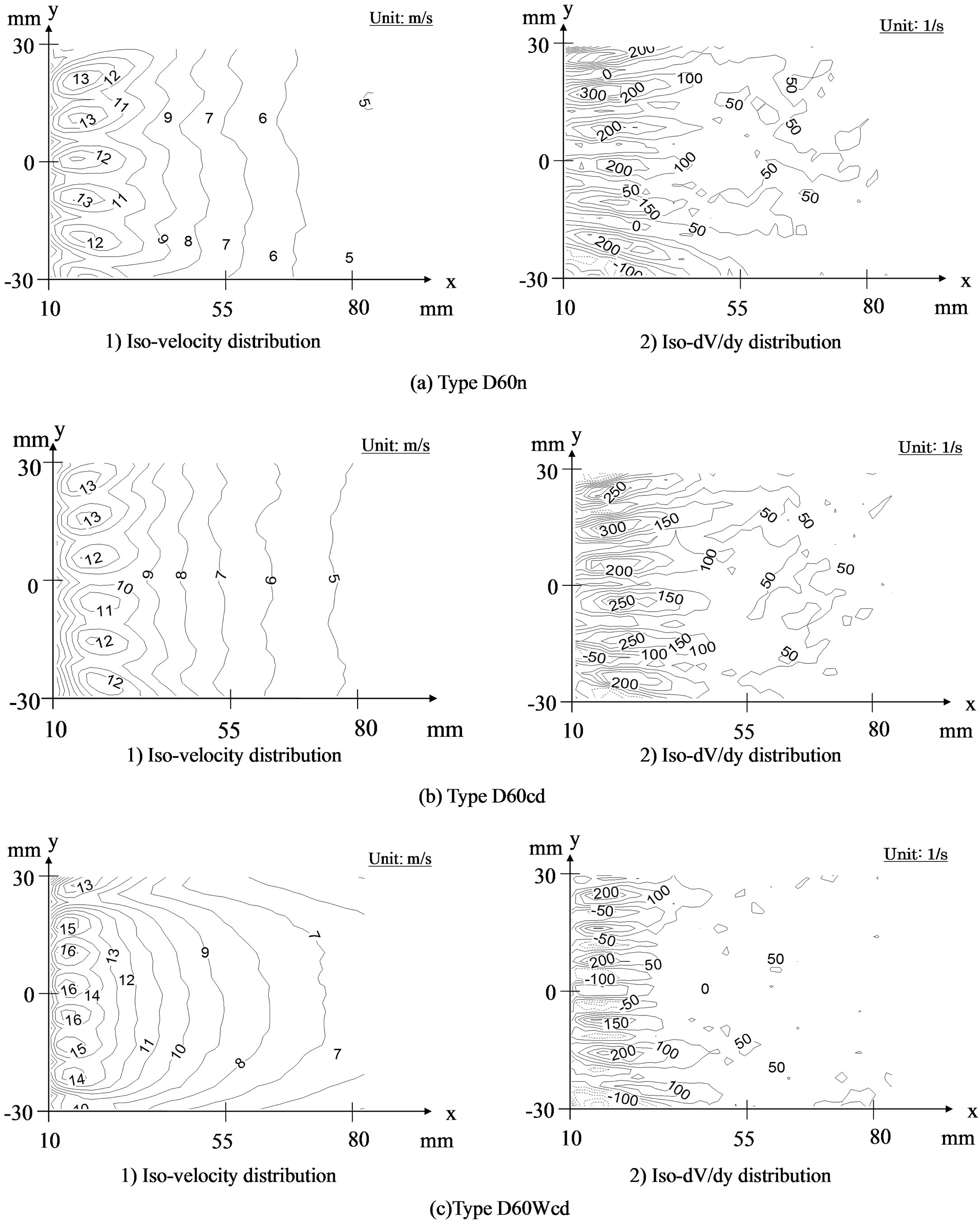
Figure 10. Velocity distributions of jet streams on a horizontal section from streamwise diverging diamond-shaped cylinder bundles.
D60n and Type D60cd, while slightly unsymmetrical flow distribution yields for Type D60Wcd, which is the streamwise velocity attenuated with an increase in y. It is found that 1) as for the iso-dV/dy which implies the jet-stream velocity-variation rate along the y-axis, Type D60cd becomes larger in the vicinity of x = 20 - 30 mm and the corresponding value is lower for Type D60n and 2) for Type D60Wcd, iso-dV/dy is low near the flow exit and is suppressed over the wide area.
Next task is to study the mean absolute values of the jet-stream velocity-variation rate, |dV/dy|, for different channels with the diamond-shaped cylinder bundle. Here, since the variation of |dV/dy| implies the mean variation of jet-stream velocity over the cross-section of the channel and the frequency of the turbulence, the value of St = |dV/dy| × d/Umax is obtained for the variation of Reynolds number. The corresponding results are depicted in Figure 11 in the form of St versus Remax for different types. Here, the measurement is carried out in the range of x = 10 - 50 mm and y = −30 - 30 mm and Remax is obtained using the maximum time-averaged velocity at the exit of channel. One observes that St attenuates with an increase in Re and for Re fixed, St is highest for Type D60cd. As for the corresponding horizontal flow oscillation of the jet-stream, the jet-stream velocity-variation rate, i.e., the variation rate of the high frequency region for Type D60cd becomes larger than that for Type D60n in the absence of the concavity. It is postulated that higher velocity-variation rate is attributed to the presence of the wake. On the contrary, even if the concavity is constructed on the wall surface of the diamond cylinder, the velocity-variation rate for Type D60Wcd becomes lower than that for Type D60cd. This is because lower velocity variation rate, for Type D60Wcd, is caused by the wider channel cross-section at sixth and seventh row bundle of diamond-shaped cylinders. Consequently, the pressure loss of the channel in Figure 8 becomes lower, resulting in lower horizontal jet-stream flow oscillation due to the flow straight characteristic.
Based on the results obtained here and the previous results [17], it is found that 1) flip-flop flow occurs in the flow passages with the concavities constructed on both sidewalls and in the channel in which the circular concavity is constructed on both side-walls of the diamondshaped cylinder and 2) in each channel, the oscillations of flip-flop flow are also induced. That is, enhancement of jet stream dispersion in both the left and right direction is caused due to the presence of concavities than that in the diamond cylinder bundles in the absence concavity. It is disclosed, therefore, that if the channel in the presence of a diamond-shaped cylinder bundle with the fourth row bundles having an apex angle of 30˚ and the following row bundles of diamond-shaped cylinders having an apex angle of 60˚ is employed, the exit oscillation jet streams

Figure 11. Changes of St versus Remax.
and self-excited oscillations occur at an exit jet stream flow field with multiple equal flow-rate jet-stream group.
4. Conclusion
A review of the intersecting flow and flip-flop flow has performed and the corresponding flow characteristics have been summarized. Furthermore, the flow characteristics around diamond-shaped cylinder bundle revised with concavities on both bundle walls have been studied for the revised channel with a diamond-shaped cylinder bundle which is consisted of the row bundles having different apex angles in the downstream direction. As a result, pressure characteristics in the channel shown in the present study are quantitatively measured in a divergingflow region in diamond cylinder bundles with concavity and in its downstream region. In particular, the pressure loss coefficient is substantially suppressed due to an extension of the channel width between diamond cylinder bundles in the downstream region. From water-flow injection experiment, three different flow phenomena, i.e., 1) flow distribution characteristics due to variation of concavity port and channel width, 2) formation of flipflop flow and multi-uniform injection jets, and 3) average velocity gradient in the transvers flow direction have been disclosed. The effect of Reynolds number on the mean absolute values of the jet-stream velocity-variation rate has been quantitatively obtained. In other words, it has been disclosed that a) the flow dispersion becomes larger due to the presence of the concavity and b) the flow straightness takes place due to the extension of the channel width between diamond-cylinder bundles in the downstream area. In industrial applications of the exit oscillation jet streams, the proposal pertinent to the channel cross-section is clarified for mixture, stirring and washing.
5. Acknowledgements
The work was partially supported by Grant-in-Aid for Scientific Research (No. 22560180) from the Japan Society for Promotion of Science for which the authors wish to express their sincere gratitude.
REFERENCES
- H. Viets, “Flip-Flop Jet Nozzle,” AIAA Journal, Vol. 13, No. 10, 1975, pp. 1375-1379. http://dx.doi.org/10.2514/3.60550
- S. Umeda, S. Hasegawa and W.-J. Yang, “Occurrence of Flip-Flop Flows in Diamond-Shaped Cylinder Bundles,” Journal of Environment and Engineering, Vol. 2, No. 1, 2007, pp. 1-12. http://dx.doi.org/10.1299/jee.2.1
- S. Umeda, Patent No. 2841173, Japan, 1998.
- S. Umeda, Patent No. 4093272, Japan, 2008.
- N. Zhang, W.-J. Yang and Y. Xu, “Flow Characteristics in Flow Networks,” Experiments in Fluids, Vol. 14, No. 1, 1993, pp. 25-32. http://dx.doi.org/10.1007/BF00196984
- S, Umeda, W.-J. Yang and T. Tanaka, “Mechanics and Correlations of Flow Phenomena in Intersecting Ducts,” Experiments in Fluids, Vol. 17, No. 5, 1994, pp. 323-329. http://dx.doi.org/10.1007/BF01874412
- S. Umeda and W.-J. Yang, “Flow Visualization Methods in Intersecting Ducts,” Journal of Flow Visualization and Image Processing, Vol. 1, No. 3, 1993, pp. 159-170.
- W.-J. Yang and S. Umeda, “Coanda Effect and Its Role in Mixing in Intersecting Flow,” Proceedings of CSME FORUM SCGM 1998, Vol. 1, 1998, pp. 147-152.
- S. Umeda and W.-J. Yang, “Dynamic Behavior of Shear Layer in Intersecting Ducts,” 9th International Symposium on Transport Phenomena in Thermal-Fluid Engineering, Singapore, 1996, pp. 784-788.
- S. Umeda, W.-J. Yang and C.-S. Wu, “Reciprocating Bubble Migration and Flip-Flop Phenomena in Multiple Flow Networks,” Proceedings of 11th International Symposium on Transport Phenomena, Hsinchu, 1998, pp. 415-420.
- S. Umeda, A. Taniguchi, S. Hasegawa and W.-J. Yang, “Flow Instability in Diverging-Flow Region with FlipFlop Phenomenon inside Diamond-Shaped Cylinder Bundles, FEDSM2003-45133, Honolulu, 2003, pp. 1-6.
- S. Umeda and W.-J. Yang, “Diagnosis of Intersecting Flow—On Visualization of Flow Networks,” Kyoritsu Publishing Co. Ltd., Tokyo, 2007, pp. 1-11.
- S. Umeda, K. Iijima, K. Shinmura and W.-J. Yang, “Effect of Wall Concavity on Oscillations of Jet Streams from Diamond-Shaped Cylinder Bundle,” Journal of Flow Visualization and Image Process, Vol. 18, No. 2, 2011, pp. 165-183. http://dx.doi.org/10.1615/JFlowVisImageProc.2011003481
- S. Umeda, “Characteristics of Intersecting Flows in Multiple Diamond-Shaped Islands,” Journal of Flow Visualization and Image Process, Vol. 8, No. 2, 2001, pp. 165- 176.
- S. Umeda and W.-J. Yang, “Flow Characteristics inside Diamond-Shaped Cylinder Bundles,” Proceedings of International Conference on Jets, Wakes and Separated Flows, ICJWSF-2005, 2005, pp. 539-542.
- S. Umeda and S. Torii, “Flip-Flop Flow Characteristics inside Streamwise Diverging Diamond-Shaped Cylinder Bundles,” Journal of Materials Science and Engineering A, Vol. 2, No. 9, 2012, pp. 616-623.
- Y. Ohya and T. Karasudani, “A Shrouded Wind Turbine Generating High Output Power with Wind-Lens Technology,” Energies, Vol. 3, No. 4, 2010, pp. 634-649. http://dx.doi.org/10.3390/en3040634
- T. Gono, T. Syuto, T. Yamagata and N. Fujisawa, “TimeResolved Scanning Stereo PIV Measurement of ThreeDimensional Velocity Field of Highly Buoyant Jet,” Journal of Visualization, Vol. 15, No. 3, 2012, pp. 231-240. http://dx.doi.org/10.1007/s12650-012-0129-y
Nomenclature
Cp: Pressure loss coefficient in diamond-cylindrical bundle;
d: Channel width of diamond-cylindrical bundle;
dV/dy: Mean velocity variation of jet-flow over the horizontal cross section;
|dV/dy|: Absolute value of dV/dy;
Hu: Water head of upper water tank;
Pd/rg: Piezometric head at the down streamwise location in diamond-cylinder bundle channel;
Pu/rg: Piezometric head at the upper streamwise location in diamond-cylinder bundle channel;
U: Mean velocity over the cross-section of water channel;
Umax: Maximum time-averaged velocity at the channel exit of air-flow injection;
Re: Reynolds number for water-flow injection;
Remax: Reynolds number for air-flow injection;
St: |dV/dy| × d/Umax;
x, y, z: Coordinate in Figure 5.