Optics and Photonics Journal
Vol.08 No.06(2018), Article ID:85423,8 pages
10.4236/opj.2018.86015
Prediction of the Cyclic Life of Pieces with Macrocracks by Thermographic Method
Valerik S. Ayrapetyan1, George A. Kurilenko2, Aelita V. Shaburova1
1Siberian State University of Geosystems and Technology, Novosibirsk, Russia
2Novosibirsk State Technical University, Novosibirsk, Russia
![]()
Copyright © 2018 by authors and Scientific Research Publishing Inc.
This work is licensed under the Creative Commons Attribution International License (CC BY 4.0).
http://creativecommons.org/licenses/by/4.0/


Received: April 17, 2018; Accepted: June 18, 2018; Published: June 21, 2018
ABSTRACT
To improve the accuracy for prediction of cyclic life of pieces with macrocracks we propose to use a new thermographic method. Traditionally this question is solved on the basis Paris formula which connects the speed of crack growth (SCG) with Stress intensity factor K. However parameter K is not identical to the SCG because K doesn’t consider non-linear processes at the top of crack (TC). That is why the using K gives the considerable error. For overcoming this problem we proposed instead of K to connect SCG with another diagnostic parameter, such as ―increment of specific entropy for cycle (ISE) at the TC, which can be calculated with sufficient accuracy through passive temperature field on the surface of tested object. Parameter ISE can be obtained both simultaneously with building of a kinetic fatigue diagram and on the basis of measuring of temperature under exploitation of piece. In both cases the prediction of cyclic lifetime is much higher than with the help parameter K. Besides parameter ISE allows to follow the crack development inside tested object. This means that suggested parameter ISE is more universal and convenient than traditional parameter K.
Keywords:
Change of Temperature, Speed of Crack Growth, Specific Entropy, Accuracy of Prediction

1. Introduction
Under cyclic deforming of pieces with macrocrack and certain conditions some plastic domain in top of crack is appeared. As a result the crack begins its movement. As it is known, under plastic deforming of metals the most part of mechanical energy is transformed in the heat energy. Therefore, a heat source arises at the top of a growing crack. Because of high heat conductivity of metals these heat sources form a passive thermal field on the surface of testing object, which characterizes the irreversible changing in the material and has a lot of information about damaging processes. This information can be received without contact with investigated object by using up-to-date infrared equipment allows to fix the kinetics of temperature distributions near top of crack with high precision. Thermographic method, based on that phenomenon, has some advantages in comparison with traditional approaches. These advantages consist in a higher accuracy and universality, because thermographic method sufficiently enlarged range of tested pieces [1] - [7] . Note also, that Stress intensity factor K is attribute of linear continuum and doesn’t consider non-linear processes at the top of crack (TC) [1] [3] [6] [7] .
2. Objectives and Method of Research
The main problem in the thermographic method is correct choice of damage parameter. Such natural parameter is temperature. But there is essential moment. It is necessary to calculate not itself temperature in the domain of damage, but its change for sufficiently small interval of time, let us say, for one cycle of oscillation. In that case influence of background’s temperature is practically excepted.
As direct damage’s parameter we use ―increment of specific entropy in the domain for cycle. Entropy is function of state, which more full reflects all irreversible changing in domain of damaging. Besides
  calculated through increment of temperature on the surface of investigated object registered by up-to-date thermographic equipment allowing to measure it without contact with high accuracy. That is why, the thermographic method essentially increases precision of cyclic life prediction.
Traditionally this question is solved on the basis of Paris formula [6] - [12]
 (1)
(1)
or its variety
 (2)
(2)
which connect the speed of crack growth  with the maxim um value of stress intensity factor (SIF)
  or its increment
 ![]() for one cycle.
for one cycle.
In the Formulas (1) and (2)![]() ―empiricallydefinedparameters of material,
―empiricallydefinedparameters of material, ![]() m/cycle―given speed of crack growth,
m/cycle―given speed of crack growth,![]() ―parameter corresponding to
―parameter corresponding to![]() .
.
Kinetic fatigue diagrams, built by testing of some samples under different loads on the basis Formulas (1) or (2), are characterized the material of tested samples.
Integration of Formula (2)
![]() (3)
(3)
gives dependence n(l) allowing to calculate the lifetime of the piece![]() , which corresponds to the crack growth at a critical length
, which corresponds to the crack growth at a critical length![]() .
.
It must be noticed that using SIF as criterion of crack growth is often criticized at last years. SIF is attribute of linear elastic medium and using it as parameter of destruction not takes into account of many factors which have influence on the events near top of crack. It leads to essential, often unpredicted errors in cyclic life calculation.
Besides we notify the some limitations on using formula (3). These limitations connect with necessity of receipt function![]() . It leads to using of standard details for which function
. It leads to using of standard details for which function ![]() is certain. In case of cyclic life prediction for non standard pieces, that function can be received by experiment. Bun in that case it is necessary overcomes essential difficulties, connected with measuring length of growing crack especially if the crack grows inside detail.
is certain. In case of cyclic life prediction for non standard pieces, that function can be received by experiment. Bun in that case it is necessary overcomes essential difficulties, connected with measuring length of growing crack especially if the crack grows inside detail.
These difficulties to some extent are softened and overcame under using as damage parameter ―increment that part of specific entropy, produced in damage domain, which caused it’s direct heating [13] [14] :
 . (4)
. (4)
here ―specific heat capacity of material,
  and
and ―temperatures of domain at the beginning and end of given cycle.
Our investigations show that under using thermographic method it is conveniently to keep structure of (2). Corresponding formula lead to
 (5)
(5)
For prediction of cyclic life Formula (5) must be integrated and after that critical growth of crack , corresponding cyclic life
 , is determined:
 (6)
(6)
We tested some samples, produced from various materials under different loads and built kinetic fatigue diagrams (Figure 1) on the basis Formula (5). These diagrams have qualitatively the same form as corresponding diagrams built by Paris Formula (2), but our diagrams allowed to define the parameters of materials not only tested samples.
On the Figure 1 such diagrams are built after testing 10 samples, loaded bending oscillations (Figure 2). As a result we defined parameters of tested steel 20. Under p = 0.5 and m = 5.6:  m/cycle,
  .
.
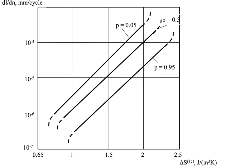
Figure 1. Diagrams  for steel 20 under various probabilities p.
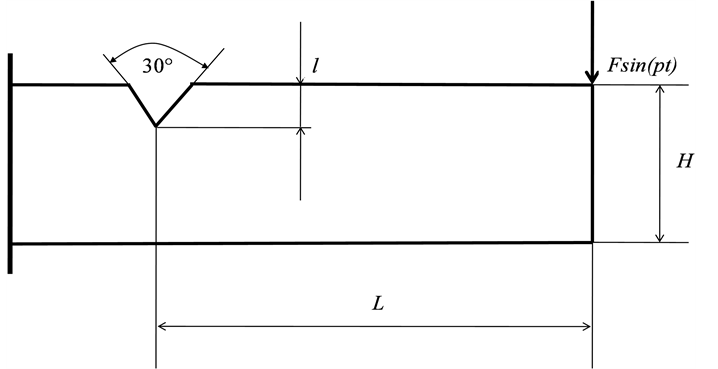
Figure 2. Sample for testing. H = 15 mm, b = 10 mm (thickness of sample), L = 260 mm, l = 0.75 mm.
These values are taken as middle point on the linear middle part of diagram, which practically defined the cyclic life of samples.
Increment of crack  for some loading cycles n is fixed by microscope “MBC-11” with net on the objective. The temperature at the top of growing crack is measured with help of thermo visor “Rubin MT”, having sensibility 0.01˚C under turned off scanning mechanism and took down by automatic apparatus “Endim-621.02”.
  is calculated by Formula (4).
Dependence  presents monotonously increasing function (Figure 3) and it can be represent as
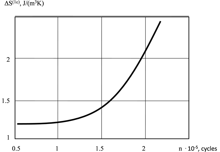
Figure 3. Diagram , built for one sample under oscillation’s amplitude of free end f = 3 mm.
 (7)
(7)
where  and
and ―empirical coefficients.
Dependence (7) under constant oscillation’s amplitude can be received by two methods:
・ direct from diagram (Figure 1); in that case function must be considered as characteristic of material and prediction of cyclic life will be probable;
・ by testing givens ample under some small cycles of loading (so keep the cyclic life), or by observing for detail under its exploitation; in that case  will be characteristic of given sample and prediction of cyclic life will be individual.
3. Results of Experiments
All tested samples are brought to destruction, and as result its actual cyclic life  is defined. Cyclic life, calculated from experiment, is defined by first method (
 ) and by second one (
 ). After that it is counted divergence
  between
 ,
,  and
and .
.
The results both experiment and calculation for one sample are showed in Table 1.
For all samples tested under one-stage loading, divergence  was less on 20% - 25% than
 . It is accounted, because under calculation
  the sample gives information about only itself cyclic life.
Thermographic method allows predict cyclic life and many-stages loading. In that case Formula (6) become as
 (8)
(8)
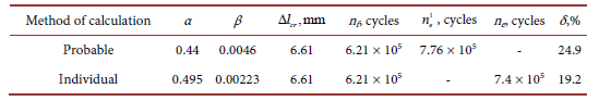
Table 1. Calculating and actual cyclic life for one sample (f = 2 mm).
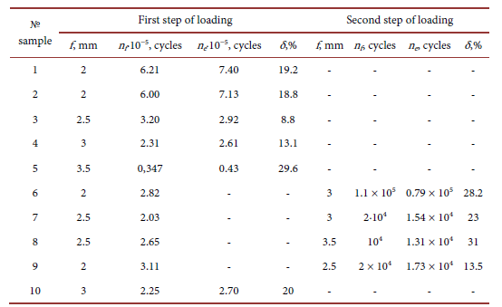
Table 2. The results of cyclic life prediction for 10 samples produced from steel 20.
With multistage loading, it is possible to consider various tasks for determining a cyclic resource. In particular, the task can be put as: the numbers of cycles n i and crack increment on the previous stages of loading are known; it is necessary to calculate the number of cycles to destruction ne on the last stage.
Peculiarity of calculation by Formula (8) consists in necessity to count over again the actual number of cycles from previous stage of loading on equivalent ones on the next stage, proceeding from the same increment of crack.
Let us examine that peculiarity at the example of cyclic life calculation for one sample on the second stage of loading (Table 2).
Let us calculate cyclic life at second stage  and compare it with
 .
.
Using Formula (7) under f = 3 mm (Figure 3) by method of least squares we receive:
 ;
; . Now we calculate equivalent number of cycles
  , corresponding crack increment to
  under f = 3 mm by Formula (6):
 ,
,
whence it follows  cycles.
Now let us define the number of cycles  under f = 3 mm, corresponding crack increment
 , whence it follows
  cycles.
Calculated cyclic life on the second stage  cycles. Error of prediction
 .
.
Similar calculation under two-stages loading fulfils for samples № 6-9 and one-stage loading for samples № 1-5, 10 (Table 2). As it follows from Table 2, error of cyclic life prediction practically not changes.
4. Analysis of the Results and Conclusions
Elaborated thermographic method for prediction cyclic life of pieces with macrocracks [1] [2] [3] [14] allows:
1) To check crack development through temperatures kinetics on the surface of tested piece without contact with investigated object by using up-to-date infrared equipment. This gives possibility to calculate new diagnostic parameter ―increment of specific entropy for cycle (ISE) at the top of crack with high accuracy. Parameter ISE can be obtained both simultaneously with building of a kinetic fatigue diagram and on the basis of measuring of temperature under exploitation of object. In both cases the prediction of cyclic lifetime is better than with the help parameter K.
2) To use (ISE) instead Stress intensity factor K ISE decreases the error of prediction in some times (not more then 30%) in comparison with Paris method, having error which can exceed 100%.
3) Considerably widen the range of objects for control, in particular, for pieces, having some difficulties for observation at crack development.
Cite this paper
Ayrapetyan, V.S., Kurilenko, G.A. and Shaburova, A.V. (2018) Prediction of the Cyclic Life of Pieces with Macrocracks by Thermographic Method. Optics and Photonics Journal, 8, 165-172. https://doi.org/10.4236/opj.2018.86015
References
- 1. Kurilenko, G.A. and Pshenichnyj, A.B. (1990) Sposob opredelenija treshhinostojkosti materialov. [The Way of Material Crack Resistance Definition.] USSR Patent No. 1820278. (In Russian)
- 2. Kurilenko, G.A. and Ayrapetyan, V.S. (2016) Determination of the Fracture Toughness of Optomechanical Devices. Optics and Photonics Journal, 6, 298-304. https://doi.org/10.4236/opj.2016.611030
- 3. Kurilenko, G.A. (1997) Quantitative Infrared Investigations through the Intensity of Thermal Source in the Domain of Damaging. Firenze, 177-188.
- 4. Hello, G., Tahar, M.B. and Roelandt, I.M. (2012) Analytical Determination of Coefficients in Crack-Tip Stress Expansions for a Finite Crack in an Infinite Plane Medium. International Journal of Solid and Structures, 49, 556-566. https://doi.org/10.1016/j.ijsolstr.2011.10.024
- 5. Dumonlin, S., Louche, H., Hopperstad, O.S. and Borvic, T. (2010) Heat Sources, Energy Storage and Dissipation in High-Strength Steels: Experiments and Modeling. European Journal of Mechanics-A/Solids, 29, 461-474. https://doi.org/10.1016/j.euromechsol.2009.11.005
- 6. Metodicheckie ukasanija (1983) Raschety I ispytanija na prochnost, metody mekhanicheskikh ispytaniy materialov. Opredelenie kharacteristik soprotivleniya razvitiiu treshchin (treshchinostoykost) pri ciklicheskom nagruzhenii. [Calculations and Tests for Durability, Methods Mechanical Tests of Materials Definition of Crack Resistance at Cyclic Load.] RD, Moscow, 96 p. (In Russian)
- 7. Romaniv, O.N., Jarema, S.Ja., Nikiforchin, G.N., Mahutov, N.A. and Stadnic M.M. (1990) Ustalost I ciklicheskaja treshchinostoykost konstrukcionnyh materialov. T.4. [Fatigue and Crack Resistance of Construction Materials at Cyclic Load. Referencebook. V.4.] Naukova Dumka, Kiev, 679 p. (In Russian)
- 8. Hellan, K. (1988) Vvedenie v mehaniku razrushenija. [Introduction to Fracture Mechanics.] Mir, Moscow, 364 p. (In Russian)
- 9. Ding, P. and Wang, X. (2010) Solutions of the Second Elastic-Plastic Fracture Mechanics Parameter in Test Specimens Engineering Fracture Mechanics, 77, 3462-3480.
- 10. Romanov, A.N. (2013) Rasprostranenie treshhin ustalosti I edinaja krivaja ciklicheskoj treshchinostoykosti konstrukcionnyh materialov. [Spreding of Fatigue Cracks and Single Curve of Cycle Resistance Crack of Construction Materials.] Problemy Mashinostroenija I Nadezhnosti Mashin, No. 5, 47-57. (In Russian).
- 11. Parton, V.Z and Morozov, E.M. (1985) Mehanika uprugoplasticheckogo razrushenija. [Mechanics of Elastic-Plastic Destruction.] Nauka, Moscow, 502 p. (In Russian).
- 12. Mahutov, N.A. and Morozov, E.M. (1982) Metody ispytanij v mehanike razrushenija. [Methods of Tests in the Fracture Mechanics.] Plant Laboratory, No. 2, 105-109. (In Russian)
- 13. Bazarov, I.P. (1983) Termodinamika. [Thermodynamics.] Vysshaja Shkola, Moscow, 344 p. (In Russian)
- 14. Kurilenko, G.A., Pshenichnyj, A.B. and Trufanova, T.V. (1992) Ocenka povrezhdaemosti ciklicheski deformiruemyh detalej s makrotreshhinami. [Damage Estimation of Repeatedly Deformed Parts with Macrocracks.] Tehnicheskaja Diagnostika I Nerazrushajushhij Kontrol, No. 3, 46-49. (In Russian)