Demonstration of Automatic Impedance-Matching and Constant Power Feeding to and Electric Helicopter via Magnetic Resonance Coupling ()
Table 1. Specifications of the resonators.

Figure 1. Wireless power transfer system for the small helicopter.
mal rated power of the helicopter’s motor. The nominal transmission distance l was set at 550 mm, which is twice as large as the average resonator diameter  of 1930 mm. Here the non-dimensional distance l' is introduced as
 (1)
(1)
The optimum impedance ratio rT is a function of QT, QR, rR, and the coupling-coefficient k as
 (2)
(2)
where Q is a quality factor defined as Q = ωL/R. Subscripts T and R respectively denote the transmitter side and receiver side. Impedance ratios rT and rR are defined respectively as rT = Zsrc/RT and rT = Zload/RR. Subscripts src and the load respectively denote the power source and external load. At l = 0, k approaches unity and rT,opt increases to 37. In preliminary testing, the impedance ratio of transmission side rT was measured to confirm that the excitation coil can satisfy Equation (2). rT is tunable by adjusting the coupling coefficient between the excitation coil and the transmitter resonator kET, as [9]
 (3)
(3)
Subscript E denotes the excitation coil. To design the excitation coil, the voltage and the current between the excitation coil and the transmitter resonator were analyzed using LTspice [10] . Table 2 presents excitation coil specifications. A pick-up coil was made of a copper-foil tube that was the same as the receiver resonator. The helicopter load resistance was assumed as 5 Ω at PT = 5 W. In this study, the receiver impedance was matched at l = 500 mm and fixed. Here, kET was measured in the same manner as k. Figure 2 portrays the measured impedance ratio on the transmitter side as a function of distance between the centers of respective coil. Results show that rT satisfied the relation of Equation (2) within the movable range of the coil. Finally, Figure 3 presents the

Figure 2. Measured rT on the transmitter side as a function of distance between the centers of each coil.

Figure 3. Measured and computed η with and without impedance matching as a function of dimensionless transmission-distance l'.
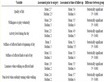
Table 2. Specifications of the pick-up and excitation coil.
measured and computed power transmission efficiency η with and without impedance matching as a function of l'. Measured values showed good agreement with the computed values. In addition, the present transmission system achieved high transmission efficiency in the low-altitude region up to 45% by appropriate impedance matching.
3. Flight Demonstration of a Toy Helicopter
3.1. Impedance Matching by Power-Reflection Monitoring
Without impedance matching, η has a peak around the designed nominal altitude. It is difficult for the helicopter to hover at a certain altitude where η increased with l'. In this sense, impedance matching is unavoidable for the helicopter to conduct a safe liftoff and landing. rT,opt was obtained by minimizing the reflection power PR. This control method is extremely simple.
3.2. Experimental Setup
A small electric helicopter with the receiver system was used in the same manner as in our previous study. As Figure 1 shows, the receiver system consists of a receiver resonator, a pick-up coil and a diode-bridge rectifier circuit. Figure 4 and Figure 5 respectively show the automatic impedance-matching system and the control flow diagram. Input power and reflected power are monitored and sent as a reference signal to a microcomputer (H8-3694F; Renesas Electronics Corp.), which controls the actuator. At several connection points where DC current flows, RC low-pass filters were used to remove the high-frequency noise. The pulse-width modulation

Figure 4. Automatic impedance-matching system for a flight demonstration.

Figure 5. Flow of the automatic-control system.
(PWM) signal is sent from the micro-computer to the actuator via a motor-driver circuit. An RF power source (T161-5613 HA; Thamway, Corp.) with maximum power of 400 W and RF frequency of 13.56 MHz was used. It enables us to monitor the input and the reflection as well as external control of the output power.
3.3. Results
As Figure 6 shows, the helicopter reached 590 mm and showed flight with impedance matching. This altitude was higher than the 500 mm designed distance. Without impedance matching hovering was difficult. Figure 7 shows the history of reflected power before and after impedance matching. At t = 0 s, PT = 8 W and PR = 3 W. The excitation coil position was out of control. When impedance matching started at 10 s, PR was 0.2 W.
4. Constant Power Feeding Demonstration
4.1. Method of η Estimation
When rR is given, η can be estimated using parameters on the transmitter side. Considering the energy losses in excitation and pickup coils, k is expressed as
 (4)
(4)

Figure 6. Automatic impedance-matching system for a flight demonstration.

Figure 7. History of reflection power. At t = 10 s impedance matching started.
where  and where
 . The subscript load denotes the load of the light bulb. k is expressed with
  as
as
 . (5)
. (5)
Substituting Equation (5) into Equation (4), η yields
 (6)
(6)
Actually, ηload is usually approximately unity. Also ηsrc and rT are given. Consequently, η can be estimated by monitoring and rT and S11.
4.2. Experimental Setup
Figure 8 portrays the constant power supply demonstration system. The reference signals of the input and reflected power sent to the microcomputer were used to estimate the transmission efficiency. The microcomputer was the same as that used in the flight demonstration. However, it was used not for impedance matching but for input power regulation from the power source to maintain 10 W at the light bulb in this demonstration. Figure 9 shows a schematic of the pick-up coil and the rectifier circuit. Table 3 shows the pick-up coil and the resonator specifications. A light bulb with rated power consumption of 10 W was used as the load on the receiver system. The constant power was demonstrated where RT and RR were pre-optimized at l = 300 mm. The measured impedance ratio rR was 9.0.

Figure 8. Constant power-feeding demonstration system.

Figure 9. Pick-up coil with the rectifier circuit and the light bulb.
4.3. Results
As Figure 10 shows, with the power control, the light bulb became bright from l = 0 mm to 300 mm. It was not bright at l = 0 mm without the power control. Figure 11 portrays the theoretical and estimated transmission efficiency η and S11 during the demonstration. Estimated η agreed well with theoretical η within 10% error. Figure 12 shows the incident power and power consumption during the demonstration. As Figure 12 shows, power consumption was regulated to approximately 10 W. Results show that it is possible to supply constant power with η estimation.

Figure 10. Pick-up coil and light bulb with ((a), (b)) and without ((c), (d)) power control.

Figure 11. Estimated and theoretical transmission efficiency without power control. l changed from 600 mm to 0 mm in 10 s and from 0 mm to 600 mm in next 10 s.
Table 3. Specifications of at the pick-up coil and a resonator.

Figure 12. Incident power and power consumption with power control. l changed from 600 mm to 0 mm in 10 s and from 0 mm to 600 mm in next 10 s.
5. Conclusions
Automatic impedance matching with WPT to a small electric powered helicopter was proposed and demonstrated. Results show that the power transmission efficiency was improved up to 45% in the high k region. The flight altitude of 590 mm was achieved with the average resonator diameter  = 1930 mm.
Furthermore, the transmission efficiency estimation method was proposed using only the properties on the transmitter side. By sliding a light bulb from 0 mm to 600 mm distant from the transmitter resonator, a constant power supply of the power of 10 W was demonstrated.