Performance Prediction of a Pressurized Entrained Flow Ultra-Fine Coal Gasifier ()

1. Introduction
Coal reserves represent the largest of the world’s energy resources estimated about 900,000 billion tons [1] . About 41% of the world’s electricity is provided by coal and an increase to 44% is expected by 2030. Coal is the only fossil fuel with the reserves to stay for more than 200 years at the current production rates compared to oil and natural gas reserves which are in the order of 40 years and 60 years [2] . Therefore, it is expected that coal will remain a potential source of energy for decades to come. Unfortunately, coal contains undesirable systems such as nitrogen and sulfur. Burning coal will release these impurities in form of NOx and SOx into the air, which can react with the air’s water vapor and form acid rain. In addition, burning coal produces carbon dioxide. Carbon dioxide in the atmosphere can trap the earth’s heat causing the greenhouse effect and changes the earth’s climate. Hence, to reduce emission of NOx and SOx, it is important to improve the efficiency of coal power generation.
The above calls on improving the coal combustion efficiency and developing new technology that can extend the usability of coal more cleanly. The high temperature gasification is one of the cleanest and most thermally efficient ways to convert the energy content from coal feeds stock into a useful product. Entrained flow coal gasifiers have been widely used in coal gasification technologies because of their high capacity and steady good performance. Also the elevated high temperature in the entrained flow gasifier guarantees a high carbon conversion in short residence time. [3] and [4] investigated the coal gasification process under different parameters, such as mixing fluctuations, which affected the volatile and gasification reaction and significantly influenced the temperature and syngas composition. However, the simulation capability for gasification was limited due to the implication of gasification reaction and low quality of the syngas produced. Computational fluid dynamics (CFD) model offers a powerful solution for understanding and improves gasification processes. Over the past decades, CFD modeling has played an important role in optimizing the performance of pulverized coal for power generation [5] . This paper is focused on the modeling of coal gasification processes to improve the understanding of the gasification processes in a two-stage entrained flow coal gasifier.
2. Model Description and Methodology
The proximate and ultimate analyses of coal particle are used is depicted in Table 1.
The modeling of coal gasification in the entrained flow gasifier is conceptually divided into four subprocesses: inert heating and moisture release, devolatilization, gas phase reactions, char gasification. These physical and chemical processes are described in the following.
2.1. Inert Heating and Moisture Release
Inert heating and moisture release the inert heating is applied when particle temperature is lower than a predefined devolatilization temperature  which is about 350˚C. This conditions may written as
 (1)
(1)
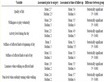
Table 1. Proximate and ultimate analysis of Kiwira Coal.
For Equation (1) inert hearting occurs when the gas temperature Tp is less that devolatilization temperature . During heating of the particles, heat transfer is only due to convection and radiation at the particle surface which is represented by the equation bellow:
 (2)
(2)
where mp = mass of coal particleCp = heat capacity of coal particleT∞ = gas temperature in the gasifier reactorh = heat transfer coefficient,
 = emissivity of coal particleσ = Stefan-Boltman constantTR = radiation temperature.
During heating particles no chemical reactions or mass transfer processes take place. The moisture released is added to the gas phase species continuity equation as a source term. The vaporization energy required for moisture release is extracted from the continuous phase.
2.2. Devolatilization
The devolatilization has a significant impact on the gasification stability and ignition. When the particle has reached an offset temperature for devolatilization  volatile matter release begins this phenomenon called devolatilization. The main species released during the volatile break up are CO, CO2, H2, CH4, O, N2, H2O, and H2S. When the particle has reached an offset temperature for devolatilization,
  volatile matters release begins. Equation (3) remains in effect until all the volatile matter has volatilized to the gas phase.
 (3)
(3)
The heat transfer to the particle during the devolatilization process governs the contributions from convection, radiation and latent heat consumed during devolatilization and it is written as shown in Equation (4).
 (4)
(4)
where;  latent heat evaporation of coal particle,
  is the rate of change of the particle.
2.3. Char Gasification
The char gasification reactions take place after all volatiles in the coal particles are released. These reactions are exothermic and take place at high operating temperatures above 1000˚C and take place until all char particles react the gasifier. The heterogeneous reactions are modeled by multiple surface reaction mechanism which already available as a sub-model in [6] . The chemical reactions in the gas-solid interaction include reaction of char particle with O2, CO2 and H2O and the major products of surface reactions are CO and H2. The reactions considered in this model along with reaction rate information are summarized in Table 2.
2.4. Gas Phase Reaction
The gas phase reactions take place in the reduction and gasification zone of the entrained flow gasifier including carbon dioxide, steam formation, water gas shift reaction and methane steam reactions. The homogeneous reactions are modeled using global reaction kinetics to describe gas phase chemistry and the kinetic parameters [7] , [8] and [9] , and [8] are given in Table 1. The turbulence chemistry interaction is modeled using a finite rate/ eddy dissipation model, a built in module in [6] , where the effective reaction rate is defined by considering the minimum between turbulence dissipation rate and chemical reaction rate.
The kinetic rate expressions for global reactions for both heterogeneous and homogeneous reactions are given by Arrhenius relationship as:
 (5)
(5)
Table 2. Kinetic rate parameters for reactions.
 where k = rate constant, A = is the pre exponential constants, E = activation energy, R = is the universal gas constant, T = is the temperature.
Multi-Phase Modeling
As mentioned earlier, the numerical method is based on a coupled Eulerian-Lagrangian formulation in which the conservation equations of the continuous phase are modeled in Eulerian frame and the coal particle trajectory is predicted in a Lagrangian reference frame. The governing equations for mass, momentum, energy and species of the continuous phase can be transformed into a general transport equation of dependent variable , written as follows:
 (6)
(6)
where  and
and  are the diffusion coefficient and the source term, respectively and these are specific to a particular meaning of
  as shown in Table 3.
3. Results and Discussion
Figure 1 shows the velocity vectors on the different position at the gasifier plane. The velocity vectors on the horizontal planes shows that the velocity near the center region of the gasifier is higher compared to the velocity in the region near the wall. Also observed in the combustor the velocity is intensity recirculating which will increase the residence time for a trapped flow and provide mixing between the unreacted coal slurry and hot gases. The observed velocity spikes about two meters gasifier height (gasifier center line) is likely due to the complex interaction of turbulent rotating flow emanating from the two bottom tangential injections causing some oscillations.
Figure 2 shows temperature distributions at different position in plane of the gasifier. Maximum gas temperature in the combustor reaches about 2900˚C. The dominant reaction in the combustor is intense char combustion and gasification reaction. Oxygen is completely depleted through the char combustion in the combustor. Gasification reactions are taking place in the upper stage on the gasifier (reductor) where most of syngas is formed. The oxidation and combustion reactions generate significant heat and temperature in the middle of first stage is rise to 2390˚K. When the hot syngas transports into the second stage, it reacts with the coal slurry, which is fed from the upper stage. There is no additional oxidant being injected into the second stage of the gasifier but slurry is injected.
Figure 3(a) shows the contours of temperature and mole fractions of H2 along mid plane in the gasifier. The H2 concentration increases along the height of the gasifier reaching maximum towards the outlet. The H2 increases rapidly in the last portion of the gasifier height due to drop of temperature resulting in most of the reac
Table 3. Variables for the generalized transport equations.

Figure 1. Velocity vector on the different position at the gasifier x-y plane.

Figure 2. Distribution of the temperature at different position in vertical plane.
tions consuming H2 do not taking place. On right hand side shows the lowest H2 consumed at first stage of gasifier during combustion process, and most of H2 form between 2 and 9 meters of the gasifier height. The last portion of the gasifier the H2 increased rapidly due to drop of temperature. Figure 3(b) shows mole fractions of CO at different position in the gasifier plane. Combustion occurs when coal slurry and oxidant are injected into the first stage of gasifier (combustor). The carbon and oxygen react immediately and generate CO. When the CO is transported into the upper stage of the gasifier, further reacts occur. The lowest CO at first stage of gasifier
 (a)
(a) (b)
(b)
Figure 3. (a) Distribution of mole fraction of H2 at different position plane along gasifier; (b) The average mole fraction of CO at different position in the gasifier plane.
because the CO is consumed during combustion process as observed in Figure 3(b). CO increases rapidly in the last portion of the gasifier height due to drop of temperature resulting in most of the reactions consuming CO do not taking place.
The complete char combustion taking place in the first stage of the gasifier produces a large amount of CO2 shown at the bottom of the reactor. As observed on the figure on right hand side (Figure 4), around 2 to 9 meters height of gasifier the CO2 is nearly constant there after drops down suddenly.
4. Conclusion
A 3D axis-symmetric CFD model is developed and the predictions of species mole fraction distribution in x-y axial direction are compared. The model is able to predict the overall trend of species distribution inside the entrained flow gasifier. Better quantitative agreement was found with H2, CO, CO2, and H2O as compared to the experimental values from the work of Martin et al. (2002) [10] . The percentage deviations are 11%, 7%, 5% and

Figure 4. The average mole fraction of CO2 at different position in the gasifier plane.
1% respectively. Detailed species distribution inside the gasifier is shown and the underlying physical and chemical processes are delineated.
Acknowledgements
I would like to thank the College of Engineering and Technology (CoET) of University of Dar es Salaam for its, financial support and the assistance to my research work.
Nomenclature
Abbreviation
CFD: Computational Fluid Dynamic
Symbols
Tp: Particle temperature Tdev: Devolatilization temperature TR: Radiation temperature T¥: Gas temperature in the gasifier reactor A: Surface area E: Activation energy R: Universal gas constant T: Temperature ep: Emissivity of coal particle Cp: Heat capacity of coal particle mp: Mass of coal particle
σ: Stefan-Boltman constant Rn: Reaction number
NOTES
*Corresponding author.