Energy-Saving and Economical Evaluations of a Ceramic Gas Turbine Cogeneration Plant ()
1. Introduction
Adaptations of aircraft engines for industrial, utility, and marine-propulsion applications have long been accepted as means for generating power with high efficiency and for ease of maintenance. Because of their heritage, aeroderivative gas turbines typically require less space and supporting structure than other industrial gas turbines of equivalent output power. These features also equate to reduced plant construction time and adaptability to meet unique requirements dictated by the site or application.
To improve the performance of gas turbines in general and the overall thermal efficiency in particular, it is necessary to increase the turbine inlet temperature. Consequently, thermal loads on turbine blades and the combustion chamber become extremely high. In such cases, modern ceramics are the best-suited materials due to their excellent high-temperature strength and other attractive properties.
In Japan, the development of ceramic components for gas turbines in cogeneration applications was initiated in 1988 by New Energy and Industrial Technology Development Organization (NEDO) sponsored by the Ministry of International Trade and Industry (MITI) [1,2]. Two types of ceramic gas turbine engines for cogeneration were built and tested. CGT301 is a restored single-shaft CGT that has characteristics for continuous full-load applications. CGT302 is a restored two-shaft CGT suitable for partial-load applications in facilities such as hotels, hospitals, and office buildings (Table 1).
Cogeneration is frequently defined as the sequential production of useful thermal energy and shaft power from a single energy source. The shaft power can be used to drive mechanical loads such as compressors, pumps, and electric generators. For applications that generate electricity, the power can either be used internally or supplied to the utility grid.
The thermal benefits of cogeneration are discussed as follows. A gas turbine cogeneration cycle is arranged to reject a portion of its exhaust energy at the temperature required in the process. The resultant system achieves approximately 75% utilization of input thermal energy compared to approximately 35% for a fossil-fuel-fired steam plant designed to provide only power. This significant energy savings is a primary factor contributing to favorable economics for many gas-turbine-based cogeneration systems.
In evaluating a power cycle, thermodynamics cannot be the only consideration. There are five general areas of

Table 1. Performance of a ceramic gas turbine (CGT302) [1,2].
concern in evaluating ceramic gas turbine cogeneration: 1) first-law efficiency, 2) second-law efficiency, 3) system performance, 4) energy savings, and 5) economic evaluation. This paper briefly describes the system under consideration, and then summarizes computational results from parametric studies.
2. Energy-Saving Evaluation
This section deals with the thermodynamic aspects of a ceramic gas turbine cogeneration system. It presents expressions involving relevant variables for fuel-utilization efficiency (first-law efficiency), electrical to thermal energy ratio (power-to-heat ratio), and second-law efficiency (exergetic efficiency). The study included the impact of atmospheric temperature on ceramic gas turbine cogeneration performance. A computer program was especially designed to calculate overall thermal efficiency and the net specific work from a simple-cycle gas turbine cogeneration system. These calculations were conducted for various combustor discharge temperatures (such as TIT) and pressure ratios. During these calculations, both partial and full loads were studied.
2.1. System Description
Currently, the simple-cycle gas turbine is the most widely used topping-cycle cogeneration systems due to its simple design. Figure l shows the flow diagram for the

Figure 1. Schematic diagram of a ceramic gas turbine (CGT302) cogeneration system.
cycle under consideration; its corresponding thermodynamic state points are described in the figure.
The operating principle of the ceramic gas turbine can be simplified as follows. Ambient air is drawn into a single-stage centrifugal compressor where it is compressed to approximately 8 atm. The compressed air then passes to the combustion chamber where fuel is injected and burned. The products of combustion enter the turbine and expand to approximately atmospheric pressure. Part of the work developed by the gas generator turbine is used to drive the compressor, while the remainder is delivered to a power turbine. The power turbine exhaust entering the heat-recovery steam generator is the waste-heat source for process heat production.
The quantity and quality of the process steam produced depends on the temperature of air entering and the temperature of steam produced in the heat-recovery steam generator. Therefore, the performance of a gas turbine cogeneration system varies significantly with compressor inlet air conditions, mainly atmospheric temperature [3]. Gas turbine design ratings are usually based on standard conditions. A popular standard is that of the International Standards Organization (ISO). The site conditions for this standard are sea-level altitude, 101.325 kPa, and 15˚C.
2.2. Performance Parameters of a Cogeneration System
The useful products from a cogeneration system are elecical energy  and thermal energy or process heat
 . A parameter used to assess the thermodynamic performance of such a system is the fuel-utilization efficiency, which is simply the ratio of overall energy in the useful products,
  and
and , to the energy of input fuel
 ,
,
 . (1)
. (1)
Another parameter commonly used to assess the therdynamic performance of a cogeneration system is the power-to-heat ratio ,
,
 . (2)
. (2)
In these parameters, power and process heat are treated equally. This reflects the first law of thermodynamics, which is concerned with the quantity and not the quality of energy. Thus, the fuel-utilization efficiency is also known as the first-law efficiency. However, according to the second law of thermodynamics, electric power is significantly more valuable than process heat. Exergy, the central concept in a second-law analysis, is always consumed or destroyed in any real process. A process is better thermodynamically if less exergy is consumed. Consequently, the ratio of the amount of exergy in the products to that supplied is a more accurate measure of the thermodynamic performance of a system [4]. By definition,
 , (3)
, (3)
where  is the overall exergy,
  is the exergy content of process heat produced, and
  is the exergy content of input fuel. The quantity
  is a second-law efficiency.
The exergy factor of process heat  and the exergy factor of fuel input
  can be defined by the following expressions:
 , (4)
, (4)
 . (5)
. (5)
Then, the second-law efficiency may be written as
 . (6)
. (6)
The exergy factor of process heat is always less than unity. In the case of saturated steam, it increases with the pressure of steam produced. This is consistent with the second law of thermodynamics because the quality of the energy content in high-pressure saturated steam is greater than the quality of the energy content in low-pressure saturated steam. The exergy factor of fuel input is close to unity for most fuels because the chemical energy in fuel is essentially overall exergy [5]. Thus, the secondlaw efficiency is not very sensitive to the exergy factor of the fuel used in cogeneration systems.
For a typical cogeneration system with process heat in the form of saturated steam,  is in the range 0.25 - 0.4, and
  is usually less than unity. Thus,
  is significantly less than
 , and an evaluation of thermodynamic performance of a cogeneration system based on the first-law efficiency alone could be misleading [5].
2.3. Results and Discussion
The thermodynamic performance of a ceramic gas turbine cogeneration system was studied. Pertinent data are shown in Table l [1,2]. With this information, only a procedure for calculating the quantity and quality of process heat produced is required. Then, the fuel-utilization efficiency, power-to-heat ratio, and second-law efficiency can be calculated.
Overall thermal efficiency and net specific work were calculated for various values of TITs and pressure ratio. The values of maximum TIT were taken to be 900˚C, 1000˚C, 1100˚C, 1200˚C, 1300˚C, 1350˚C, and 1400 C, while the values of pressure ratios used in the calculations were 2, 4, 6, 8, and 10.
Figure l shows the simple-cycle ceramic gas turbine arrangement considered in this study. Fuel gas was used in this analysis; however, the properties of any type of fuel can be fed to the computer program. Efficiencies of the compressor, turbine, and combustion chamber were assumed to be 82%, 84%, and 99%, respectively. These assumptions were taken from catalogs provided by manufacturers and are expected to lead to realistic computational results.
Figure 2 shows thermal efficiencies at different maximum TITs. TIT increases with the thermal efficiency.
The effect of atmospheric air temperature on thermal efficiency is shown in Figure 3. These values of thermal

Figure 2. Overall thermal efficiency with various turbine inlet temperatures.

Figure 3. Overall thermal efficiency with various atmospheric temperatures (TIT = 1350˚C).
efficiency decrease as the atmospheric air temperature increases for the same TIT (1350˚C).
Increases in the pressure ratio increase the thermal efficiency in some cases considered here. For pressure ratios less than 8, the increase in the pressure ratio causes an increase in the thermal efficiency for a constant maximum inlet temperature of 1350˚C, as shown in Figure 3. Above a pressure ratio of 8, increases in the pressure ratio decrease the thermal efficiency at all values of the assumed atmospheric temperature. However, at higher values of the atmospheric temperature, the rate of increase in thermal energy with pressure ratio becomes smaller.
The calculated exergy flow and energy flow are represented graphically in Figures 4 and 5, respectively. The lower heating value of the fuel represents 100% of the exergy input into the process. This input to the fuel is converted into two exergy flows and a loss. The exergy fed to the ceramic gas turbine is converted into electrical energy, waste heat in the gas, and a loss because of combustion. The heat-recovery system produces saturated steam from the heat of the waste gas. For the ceramic gas turbine cogeneration process, it is 49.4 J per 100-Joule input, which means an overall efficiency of 49.4%.
The exergy flow of a conventional gas turbine cogeneration process differs from a ceramic gas turbine cogeneration process because the maximum TIT (900˚C) for the conventional process is lower than that in the ceramic turbine process (1350˚C). Only the amounts of the exergy flows differ. The conversion efficiency from fuel to electricity is 25.8%. Apart from this, the exergy flow is similar to that in the ceramic gas turbine cogeneration process.
To compare the two processes, characteristic data are condensed in Table 2. The boundary conditions for the two plants are the same. Large exergy losses become visible in all combustion process, e.g., for the combustion in gas turbines. The other conversion losses are comparatively small.
According to the second law of thermodynamics, the useful heat and power delivered by a cogeneration plant do not have the same unitary value, although they are quantified in the same physical unit, Joule.
Electricity is a form of “pure exergy”, while the heat contained in process steam has an exergy content (or economic value) that depends on the temperature at which it is available. Figure 4 presents exergetic diagrams relative to the production of heat and power by typical process units. These diagrams clearly show that some of the heat cannot be converted into useful work.

Figure 4. Exergy flow diagram of a ceramic gas turbine cogeneration system.
This results from internal irreversibilities caused by imperfections in the conversion process; it measures the degradation of energy entering the process (fuel) whose exergy content is close to unity.
The situation is different in electricity production where only the exergy from the process is taken as the useful output. This explains why thermal efficiencies based on the first law of thermodynamics easily reach 67% in Figure 5, while this sophisticated power plant hardly achieves 50% efficiency.
3. Economic Evaluation
3.1. Definition of Energy Demand
In most cogeneration plants, both thermal and electric power demands experience wide variations over time. Since the selected time step is 1 h and the plant simulation is to be performed over an entire year, the most general format of input data necessary to define each case would comprise an array of 8760 values. Besides making load specification very unpractical, such a format would also require exhaustive computing times. On the basis of the author’s experience, the following simplified assumptions yield a sufficiently accurate load description for most practical situations.
Monthly load variations can be described by specifying the minimum and maximum electric and thermal demands. Hourly fluctuations between the minimum and maximum demands are described by means of a daily load profile that is made dimensionless with respect to the total demand. Notice that the magnitude of the total

Figure 5. Energy flow diagram of a ceramic gas turbine cogeneration system.
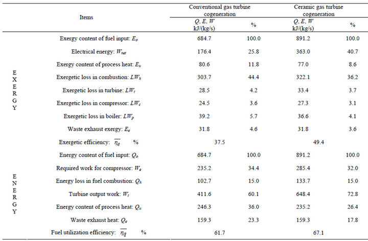
Table 2. Exergy and energy balances.
demand used for scaling daily profiles can change from month to month. It is assumed that there are only two types of daily dimensionless profiles, one for weekdays and the other for weekends. A further distinction is introduced between summer and winter. Thus, the entire year can be described by four daily profiles.
Under these assumptions, an entire year can be simulated by optimizing only 24 days (two days for each month); this results in substantial savings in computing time. In most practical cases, the accuracy of the results is much better than that of the load description.
The maximum and annual demands at a hotel, a hospital, and an office building in Tokyo are shown in Table 3 [6]. Monthly energy usage was allocated to both peak and off-peak periods. Hourly data on electric demand were provided by the electric utility. The seasonality of demand variations is the average weekday demand shown for each of the two types of area of buildings of months. Monthly fuel usage was taken from daily boiler logs. While all boilers were capable of firing oil, only natural gas was used.
3.2. Estimation of Energy Saving
To estimate the energy savings available from ceramic gas turbine cogeneration, the “energy saving ratio” is defined as the ratio of energy saved by cogeneration to fuel consumption in a “conventional” system. In the conventional system, electric power is purchased from a utility (with 35% efficiency), and heat is produced by a boiler (with 90% efficiency). From the anticipated energy savings by cogeneration, a relationship was obtained between energy saving ratio and electric power supply per maximum demand in buildings. Using this relationship and the demand distribution in buildings, energy savings were estimated.
In the simulation model of the ceramic gas turbine cogeneration plant shown in Figure 6, the source energy consumption of the system was estimated hourly. These estimates were based on shaft power and recovered heat, which were calculated from the partial-load efficiency of a ceramic gas turbine, waste-heat recovery boiler, and economizer.
Using parameters of the generating efficiency of electric power, the overall efficiency of energy utilization under partial loads, and the energy saving ratio, a plot of potential energy savings can be created, as shown in Figure 7. Figure 7 indicates the values for energy saving index of the hotel (20,000 m2), the hospital (20,000 m2) and the office building (20,000 m2). This figure relates the energy saving ratio to the energy demand distribution. It is assumed that there are only two types of ce-

Table 3. Energy demand in buildings [6].

Figure 6. System diagram of a ceramic gas turbine cogeneration plant.
ramic gas turbines, as shown in Figure 7: fully loaded and partially load. The fully loaded engine is CGT301, whereas the partially loaded engine is CGT302. The maximum saving energies in the partially loaded type for the hotel and hospital are higher than those in the fully loaded type. In the range of electric power supplied per maximum demand, especially at lower values of supplied electric power, a large energy saving is not expected.
3.3. Analysis of Energy Cost
When comparing the ceramic gas turbine cogeneration
 (a)
(a) (b)
(b) (c)
(c)
Figure 7. Values for energy saving index (20,000 m2) in a (a) hotel, (b) hospital, and (c) office building.
system with a conventional system, care must be taken to properly evaluate the unit energy costs in each case. With cogeneration, electric utilization and contractual power are generally lower, implying higher electricity costs. Moreover, the “value” for heat depends on the user’s characteristics. Considering an example of business and commercial use, a “value” for heat may be simply obtained as the product of the heat demand and the unit cost of fuel used in the conventional system; but such a fuel cost can be the same as, lower than, or higher than that for the cogeneration plant. Considering the user’s characteristics, the computer program requires a “value” for the cogenerated heat that must consider all differences in fuel costs and efficiencies between the cogeneration and conventional cases [7].
Supplemental power costs, which are defined as the cost of power purchased from the utility on a regular
 (a)
(a) (b)
(b) (c)
(c)
Figure 8. Values for economical index (20,000 m2) in a (a) hotel, (b) hospital, and (c) office building.
basis, and supplemental fuel costs, which are the costs of fuel required for the conventional boiler and the duct burner, were computed. The payback periods through cost savings derived from the efficiency of the ceramic gas turbine cogeneration system for each building are shown in Figure 8. Figure 8 indicates the values for economic index of the hotel (20,000 m2), the hospital (20,000 m2) and office building (20,000 m2). The incremental costs of operating this system are also presented. In the low range of electric power supply per maximum demand, the capacity of the ceramic gas turbine cogeneration system is designed for payback periods of less than five years in the hotel and hospital.
4. Conclusions
Many useful expressions have been developed for the study of a ceramic gas turbine cogeneration system. Some of the importance conclusions are as follows:
1) Specific output power, specific process heat production, fuel-utilization efficiency, and second-law efficiency improve with increases in the maximum inlet temperature.
2) Second-law efficiency and power-to-heat ratio are better indicators of thermodynamic performance than fuelutilization efficiency.
3) In the high range of electric power supply per maximum demand, maximum energy savings are realized.
4) The capacity of the system is designed for payback periods of less than five years through cost savings derived from improved system efficiencies.
Nomenclature
 : waste exhaust exergy kJ/(kg/s);
 : exergy content of fuel input kJ/(kg/s);
 : exergy content of process heat kJ/(kg/s);
 : mass flow rate in gas turbine cycle,
  1 - 11 kg/s;
 : mass flow rate of fuel in gas turbine cycle kg/s;
 : exergetic loss in compressor kJ/(kg/s);
 : exergetic loss in combustion kJ/(kg/s);
 : exergetic loss in boiler kJ/(kg/s);
 : exergetic loss in turbine kJ/(kg/s);
 : pressure in gas turbine cycle,
  1 - 11 kPa;
 : waste exhaust heat kJ/(kg/s);
 : energy loss in fuel combustion kJ/(kg/s);
 : energy content of fuel input kJ/(kg/s);
 : energy content of process heat kJ/(kg/s);
 : power-to-heat ratio;
 or
or : temperature ˚C;
 : temperature in gas turbine cycle,
  1˚C - 11˚C;
 : turbine inlet temperature ˚C;
 : required work for compressor kJ/(kg/s);
 : electrical energy kJ/(kg/s);
 : turbine output work kJ/(kg/s);
 : exergetic efficiency (second-law efficiency) %;
 : fuel-utilization efficiency %;
 : overall thermal efficiency %;
 : exergy factor of fuel input (
 );
);
 : exergy factor of process heat (
 );
);
 : pressure ratio.