
1. Introduction
The assembly processes design remains an area in which the use of computer aided design tools is small and depends on subjective, human factors. First of all, this is due to the design patterns informality, the inadequate capabilities of 3D and solid modeling tools, the need to combine computational capabilities with artificial intelligence methods.
Modern technological processes CAD (computer-aided design) systems used in robotic production usually provide a learning mode implemented using a software interface. For example, in [1] software enables to exchange data through supply chain network; in [2] hexapod work space is analyzed using integration of a CAD/CAE system. However, in this case, such an interface is not always able to accurately convey the requirements of the designer. For example, some values of the coordinates of points, speed parameters and directions of movement may be incorrect. An expedient way to solve the problem is to introduce an interactive mode of control and design of technological processes and, as an option, the introduction of voice control. In [3] mobile assistive robot is designed to support older persons in their private home, and the voice control is useful. In [4] audio information is used for robot motion control.
Using voice control will improve the accuracy of the necessary binding of the robot to the coordinates of the working area, including the situation of its dynamic change. In this case, the operator, using voice control, can orient the manipulator in those positions of articulations and those coordinates that are required for performing technological transitions and operations. Using this method, it is possible to significantly simplify assembly technology process design, to perform robotic system functioning operational control. We can see all these advantages in [3] [4] and in others.
2. Materials and Methods
2.1. Voice in the Control System
Voice control problem is considered by many authors. L Muda, M Begam, I Elamvazuthi [5] propose to use Mel Frequency Cepstral Coefficients (MFCCs) as extraction techniques and Dynamic Time Warping (DTW) as features matching techniques. Y. M. Yu, G. Q. Zhao, T. C. Du [6] implemented voice recognition robot by combining of toy robot and a microcontroller SPCE061. Tasevski Jovica, Nikolić Milutin, Mišković Dragiša [7] report a solution for the integration of the industrial robot ABB IRB140 with the system for automatic speech recognition (ASR) and the system for computer vision. Neng-Sheng Pai, Hua-Jui Kuang, Ting-Yuan Chang, Ying-Che Kuo, and Chun-Yuan Lai [8] propose to use after the speech pre-processing of this speech database, the feature parameters of cepstrum and delta-cepstrum were obtained using linear predictive coefficient (LPC) and then to use Hidden Markov Model (HMM) for model training of the speech database, and the Viterbi algorithm was used to find an optimal state sequence as the reference sample for speech recognition. K. Kannan, Dr. J. Selvakumar [9] in their paper “Arduino Based Voice Controlled Robot” describe their EasyVR module, which they train to recognize commands, but there is no detailed description how they recognize them. N. Manish and B. Jagadeesh Reddy [10] propose to use Microsoft Speech API but they don’t take into consideration fuzzy commands. Panek P., Mayer P. [3] propose to use a commercially available automatic speech recognition (ASR) serves as base. Mayank Gupta, Pulkit Verma, Tuhin Bhattacharya, Pradip K. Das [11] propose algorithm that is rather interesting but it is not good for industrial conditions. Stanislav Ondas, Jozef Juhar, Matus Pleva, Anton Cizmar, Roland Holcer [12] use HMM- based acoustic models trained using the SpeechDatE-SK database. Alberto Poncela and Leticia Gallardo-Estrella [13] use Simon, Sphinx, and Julius/Julian.
In every specific condition we can use different methods. We have to understand the main goal. It may be either the highest working speed or the biggest vocabulary or usefulness for the specific language and so on. According to the goal we can choose different methods and approaches.
2.2. General Ideology of Processing Voice Information
Speech recognition process requires specific procedure. It may be described as next sequence. First of all we have to get entire audio information. Then it is necessary to eliminate noise and silence, so to get clear voice. We distinguish separate words audio information energy. Voice information has greater energy then audio without voice. Then we can use different algorithms to recognize words.
For robot control implementation authors propose different methods for preliminary sound processing such as Mel Frequency Cepstral Coefficients (MFCCs), Dynamic Time Warping (DTW) [5] .
After preliminary processing linear predictive coefficient and Hidden Markov Model [8] [12] for model training of the speech database [8] and SpeechDatE-SK database, and the Viterbi algorithm was used to find an optimal state sequence as the reference sample for speech recognition. For recognition a lot of authors propose to use Microsoft Speech API [10] , commercially available automatic speech recognition (ASR) [4] [7] , Simon, Sphinx, and Julius/Julian [13] , API Google [14] but it is not specified, in what way control commands library is organized. Many authors propose working algorithms for toy robots [6] , and robots based on Arduino [9] , such robots cannot be used in industrial conditions.
Automatic speech recognition methods recognize user’s speech and are determined by grammars. If sequence included into grammars is recognized recognition mechanism event, which can be processed by application and planned action is performed.
There are three methods for grammars definition: XMl-files using [15] [16] , binary configuration files (CFG) using [17] or grammars and data structures compiler methods using [18] .
Using XML files is the most convenient way to define grammars [15] [16] . This position may be explained by the fact we can create XML-file that will have specific structure. It may be hierarchical. And recognition system after every word is waiting for one word from limited vocabulary. So first of all it waits for word “robot”, then for movement type―“rotate” or “move” and so on.
For command implementation using XML-file next action sequence is used:
1) Commands block description begins with a key (pre-control) word, for example “Robot”;
2) The second command phrase word determines movement type: turn (rotate) or move to a point (move).
3) Subsequent words constitute parameters associated with a particular command.
4) The phrase ends with the word “end”, which indicates that the command has been completed and now it is necessary to start checking it for correct assignment and execution.
3. Results and Discussions
So we took an XML-file for library constructing. And for robot voice control system we have to choose such programming environment that may use developed library. Based on the analysis of automatic speech recognition technologies implemented on personal computers, we chose Microsoft Speech Engine as a technology that integrates well with operating systems and is used for HMI (Human Machine Interface), production cell management and dispatch management.
So let us consider library with specified structure development. Used grammar is composed by the type “TopLevelRule” with a predefined initial state, that is, the automatic speech recognition system looks for the pre-control word “Robot” as a precondition to any recognizable command line. This sequence of words makes rules of the second level, and they are used in “TopLevelRule” and are not directly recognizable. The rule is defined for each planned action. Here is the syntax of the command:
Robot
end
where “Robot”?pre-control word,
?word that determines movement type,
?words associated with the command,
“end”?word that indicates command input finish.
Using previous statements and positions a software for robot voice control was developed. The main window is shown in Figure 1.
The “StartControl” button connects the robot to control from a personal computer. “StopControl”?disables the robot from the personal computer. The “Manual Ctrl” and “Angle Ctrl” switches allow selecting either a step-by-step moving of the robot, or moving to the corners, respectively. The rotation angle is set by the number in the special control.
The buttons “Base”, “Shoulder”, “Elbow”, “WristRotate”, “WristDown” and “Gripper” allow selecting the link of the robot that needs to be rotated. To initialize the motion or delay, there is a “Move Init/Move Delay”.
In the window, you can select the speed of the robot using the “SliderCtrl” element, the speed value will be indicated in the “Edit” element (in this case, the speed is 7). The “OpenGL” button brings up a window in which the robot’s work is simulated. The “Voice Control” button calls the recognition window, this window, in which the command is directly assigned and checked for compliance with existing tokens, it is shown in Figure 2.
When the program is running in recognition mode, XML files are used as a standard grammar description tool for the Microsoft Speech API 5.1 library.
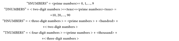
When composing a library of words that can be used in the robot control program text, the following identifiers are also indicated: “words”, “switch”, “joint”, “NUMBERS” (Numbers), “SNUMBERS” (numbers pronounced by one word), “DNUMBERS” (two-digit numbers), “HNUMBERS” (three-digit numbers), “TNUMBERS” (four-digit numbers). The presence of such sections number is explained by English language peculiarities-the language of robot control by means of voice. The numbers from one to twenty are single-word, that is, they can be given by pronouncing one word. Numbers such as “twenty-one”, “twenty-two”, and so on, contain two words in their composition, the first of which denotes tens, and the second?the number from one to nine. Three-digit numbers, for example, “125”, are pronounced in English as “one hundred and twenty-five”. Thus, this number includes in the first place a number from one to nine, indicating the number of hundreds, followed immediately by the very word “hundred” (“hundred”), then either a one-word number (one to twenty),
or a two-word number . Similarly, you can represent numbers from a thousand to twenty thousand. The number “1125” (four words in Russian) in the English version will sound like “one thousand one hundred and twenty-five”. Here in the first place is the number denoting the number of thousands (from one to twenty), then the word “thousand” (“thousand”) and then everything is analogous to the representation of a three-digit number.
In the “words” section the words “robot” (the beginning of the command), “end” (the end of the command), “exit” (exit from the program) are indicated. In the “switch” section, the words denoting the action type “rotate”, “move” are displayed. The “joint” section includes the names of the links “base”, “shoulder”, “elbow”, “wristrotate”, “wristdown” and “gripper”.
“HNUMBERS”, “TNUMBERS”, each of which has its own structure. “SNUMBERS” includes prime numbers, “DNUMBERS”―tens and prime numbers (“SNUMBERS”), “HNUMBERS”―hundreds and “DNUMBERS”, “TNUMBERS”―thousands and “HNUMBERS”.
To specify control commands, they must be pronounced strictly in the order corresponding to existing lexemes. That is, first of all, the pre-command word “robot” is pronounced, followed by the movement type command (“rotate” or “move”). Further, in the case of movement of the “rotate” type, the name of the robot link (“base”, “shoulder”, “elbow”, “wristrotate”, “wristdown”) or “gripper” (grasp).
If you want to rotate in the negative direction (counterclockwise), the word “minus” is pronounced and then the number corresponding to the rotation angle (in the case of the positive direction of rotation (clockwise), the word “minus” is not pronounced).
For example, you need to set the rotation of the robot column to 125 degrees (that is, counter-clockwise). For this, the following command is formed by voice:

In the case of movement of the “move” type, a triple of numbers is assigned after the given word, corresponding to the values of displacements along the coordinate axes x, y, z. The numbers are separated by a dot-delimiter “dot”, which denotes the end of the previous number. Similarly to specifying a degree measure of the rotation angle in the “rotate” command, if necessary, in this command, you can set the movement in both the positive direction and the negative direction. If the word “minus” is missing in any coordinate, then moving along this axis should be done in the positive direction. Coordinates are given in strict order: the first number corresponds to the movement along the x-axis, the second-along the ordinate y, the third-along the z-axis. The introduction of only one number means movement only along the x axis, two numbers in the x and y directions. If you need to move along the y and z axes, and there is no x axis, first you set 0, and then move along the necessary axes. Similarly, you can move only along the axis of the applicator: first two zeros, and then the desired number, corresponding to the movement along the z axis. In the same way, any combination of movements of the robot arm grasping along the necessary axes is specified.
Consider an example command:
robot
move twenty one dot minus nine dot five hundreds forty six
end.
The above example specifies the movement of the manipulator grasp to a point with coordinates (21, −9, 546).
―the end of the command (the verification program comes to the word “end”);
―detection of an error in the specified command (if the program finds an error in the command of any command, the execution of the commands is terminated).
Below is an example of setting several subcommands in the same command.
robot
rotate shoulder fifty three
move zero dot twelve dot minus seventy eight
rotate elbow minus ninety
end.
This command assumes the following actions: rotation of the robot shoulder by 53 degrees, then moving the manipulator to the point with coordinates (0, 12, −78) and the subsequent rotation of the robot’s elbow by −90 degrees.
To ensure voice control, follow the sequence below:
1) Place the objects in the working area of the robot (as a rule, the component parts are located in the next cell of the working area).
2) It is necessary to teach the robot the points of location of the main assembly parts. To do this, use the combination of “rotate”, “move” and “fix” commands.
3) A number of commands can be compound, they should be combined into meta-commands, for example, “take object A”, “place object A at point B”.
4) Using the control commands of the manipulator and meta commands to set the necessary technological transitions and operations.
5) Verify the correctness of the generated process by repeating the assembly process of the product.
In some cases, when designing assembly processes, the operator can not specify the exact commands that would fully ensure the execution of the necessary technological transitions and operations. In such cases it is advisable to use fuzzy commands, for example, “slightly to the left”, “even higher”, “forward”, etc.
Consider fuzzy commands corresponding to the shifts “left”, “right”, “forward”, “back”, “up”, “down”. We will estimate these displacements with the help of the concepts “more”, “left/right/forward/back/up/down”, “a little to the left/to the right/forward/back “ (Slightly left, right, forward, back, up, down) and a “little bit” (a bit). The degree of displacement is shown in Table 1.
When using the “rotate” command in this case, the “left” offset is taken as the rotation of the link in the counterclockwise direction, and the “right” shift is the clockwise rotation of the link. If fuzzy shifts are specified in the text of the “move” command, then the “left” offset corresponds to the movement of the robot arm grasp in the negative direction along the abscissa (x), “right”―move- ment in the positive direction along the x, “forward” and “back” axes (Y), the use of the word “forward” implies a shift in the positive direction, and “back” in the negative direction, respectively, the “up” and “down” shifts determine some movements from the z-axis (z), here “Up” denoting m positive direction of movement, and the “down”―negative.
The minimum offset is 10 mm and the maximum offset is 400 mm. Formalization of such a description for a left bias formalization of such a description can be carried out with the help of the following linguistic variable <β, T, X, G, M>, where β is the name of the linguistic variable; T is the set of its values, which are the names of fuzzy variables, the domain of definition of each of which is the set X; G-syntactic procedure (grammar), allowing to operate with elements of set T; M is a semantic procedure that allows each new value of a linguistic variable, formed by procedure G, to be transformed into a fuzzy variable. In this case, β is the value of the displacement to the left; T = {α1, α2, α3, α4} = {slightly to the left, slightly to the left, to the left, to the left}; X = [10, 400].
Similarly, all linguistic variables can be represented. It should also be noted that quantitative values corresponding to different degrees of bias are determined by experts. In this case, when using the “move” command, “slightly to the left” corresponds to a 10 mm offset in the negative x-direction, “slightly to the left”―100 mm, “left”―200 mm, “even more left”―400 mm. We construct the graphs of the membership of fuzzy sets (Figure 3, Figure 4).
Similarly, you can describe all other linguistic variables when using them as part of the “move” command. In the case of the “rotate” command, only the variables “to the left” and “to the right” are applied. For them, the degrees of rotation are assigned the following values: “slightly to the left”―a turn of 10 degrees in the negative direction, “slightly to the left”―to 30 degrees, “left”―to 60 degrees, “more left”―to 90 degrees, all values for The degrees of rotation when
![]()
Figure 3. Graphs of belonging for a fuzzy variable “to the left”.
![]()
Figure 4. Accessory charts for a fuzzy variable “to the right”.
using the variable “right” are stored with an accuracy to the sign, which corresponds to a rotation in the positive direction.
Thus, the software for voice control of the robot has been developed. The requirements to the working language of the voice control system have been formulated. The library of the words of the working language of the system that make up the working language of the robot is proposed.
The shortcomings of the proposed development include the limited scope of the language of management, as well as the formalization of each phrase that is not natural to the natural language. The advantage is the presence of a key pre-control word, thus it is possible to operate the system in a noisy room.
4. Conclusions
The article considers robot voice control software development. Program main window is displayed, as well as the recognition window, in which the operator can check the correct recognition and interpretation of voice commands. We consider the controls that are present on these windows. Control command structure is developed with a detailed description according to the prevailing grammar. To control the robot, it is necessary to compile a library of words that the operator can input to achieve the set goals. The main elements of this library are discussed and defined through the article. To provide voice control, a sequence of actions is provided, which must be followed by the operator. Also, the commands that may be needed in the case of interactive correction of actions are considered.
Thus, the developed software allows providing industrial robot voice control and can be used in the subsequent design of technological transitions and operations in robotic production technological processes design. We can also combine this software with the ideology of image processing or the methodology of wavelet analysis [19] - [24] . This will create a variety of applications for the use of robots.