Journal of Power and Energy Engineering
Vol.07 No.09(2019), Article ID:95245,10 pages
10.4236/jpee.2019.79005
Design and Enhancement of Thermal Flow Characteristic in an Annular Diffuser under Turbulent Flow
Ehan Sabah Shukri Askari
Engineering Technical College-Baghdad, Middle Technical University, MTU, Baghdad, Iraq

Copyright © 2019 by author(s) and Scientific Research Publishing Inc.
This work is licensed under the Creative Commons Attribution International License (CC BY 4.0).
http://creativecommons.org/licenses/by/4.0/


Received: June 28, 2019; Accepted: September 21, 2019; Published: September 24, 2019
ABSTRACT
The annular diffuser is an expansion area, which, despite its simple structure, is very important in some engineering and thermal applications. In the present research, numerical simulations were performed to investigate the temperature field and flow structure characteristics in an annular diffuser. The hub of the annular diffuser consisted of a straight semi-dimpled tube SSDT. Three different diffuser wall angles (α) 1.8˚, 3.6˚ and 5.4˚ with inlet Reynolds number 1.5 × 10⁴ were studied in details with air as a working fluid. The computational fluid dynamics CFD was used to simulate the model in a turbulent flow. The standard k-ε turbulence model was used to complete the governing equations. The numerical results, mainly the temperature distribution, pressure drop and velocity distribution for the airflow in the annular diffuser fitted with SSDT for different diffuser wall angles α were obtained and compared. It was observed that as the wall diffuser angle α increases, the enhancement of the temperature distribution and the velocity distribution decrease while the pressure drop rate increases. The maximum temperature distribution and velocity distribution were completed by diffuser wall angle α1 = 1.8˚ whereas, the highest pressure drop achieved by diffuser wall angle α3 = 5.4˚.
Keywords:
CFD, Turbulent Flow, Temperature Field, Annular Diffuser, Semi-Dimples

1. Introduction
Thermal properties enhancing techniques are very required by many industrial and engineering applications, including gas turbine, heat exchanger, boilers, and solar thermal devices. Dimples are one of the designs that have very strong industrial significance. It is used to induce a tangential velocity component and to increase recirculation during the flow [1] - [5] . In recent years, the cost of energy kept going up and became higher, therefore, more focus and effort should be aimed to study these enhancing techniques. For thermal enhancement, techniques were used to enhance the thermal properties of the flow such as pins-fins, rough surfaces, pimples, and dimples in the direction of the flow, which caused redistributes thermal boundary layers and enhanced the flow turbulence. However, these techniques also caused friction loss that caused more power lost. Therefore, the effective technique should achieve a high enhancement at a low power cost [6] . For energy conservation, the most effective measurements are heat transfer enhancement and low-pressure loss. Therefore, several kinds of research have been studied the heat transfer improvement with lower pressure drop. Huancheng et al. [7] investigated the flow and heat transfer characteristics of a rectangular channel with arrays of dimples among transitional Reynolds number. The results discussed different dimple depth and different Reynolds numbers. The obtained results indicated that the velocity got plumper in the transition region and the averaged Nusselt number decreased in the flow direction when it was under laminar condition while it increased when the flow was under turbulent condition. In addition, at the turbulent flow region, the heat transfer was enhanced by the dimple and it increased with the dimple depth. The flow characteristics induced by inserting dimples got a lot of attentions [8] [9] [10] . Computational Fluid Dynamics (CFD) is commonly used for this purpose. A numerical study with dumbbell-shaped dimples was performed in a rectangular channel [8] . The findings were provided by comparing the numerical solution results for the flow in a rectangular channel with a single spherical dimple with experimental data for known research. The study showed up to 5 % lower pressure loss of channel with dumbbell-shaped dimples compared to one with spherical dimples. L. Binci et al. [9] studied the flow field around a dimpled NACA 64-014A laminar airfoil. The research aimed to evaluate the effect of dimples on the laminar separation bubble (LSB) reduction numerically. In order to get specific results, the simulations carried out with two types of turbulence models; Reynolds Averaged Navier-Stokes (RANS) equations and Large-Eddy Simulations (LES), which were compared with wind tunnel measurements in order to estimate their effect in the modeling this type of flow. They concluded that both numerical models showed a total drag reduction. These findings were very interesting because by using dimples, the drag reduced and that reduced the axial force and produced extra electric power and minor mechanical stress for a wind turbine.
The annular diffuser has received more attention during the past decade [11] [12] [13] . The effect of different diffuser geometries was studied. One of the geometries that gave important notices is the diffuser wall angles. Marothia [13] investigated the effect of different diffuser wall angles (10˚, 15˚, 20˚ and 25˚) and various area ratio AR (2, 3, 4 and 5) on the flow structures with inlet Reynolds number ranged from 260,000 to 780,000. The results detected that the diffusing angle played an important role in flow structures with almost independent of Reynolds number. Moreover, Pravin et al. [14] studied the effect of the diffuser angle and area ratio on the flow field characteristics. The findings reviled that the velocity distribution was affected by this angle more than the diffuser area ratio.
Since the value of the diffuser angle has an important affection on the flow, the present research investigated three different diffuser wall angles (α) 1.8˚, 3.6˚ and 5.4˚. Furthermore, most of the researches focused on inserting dimples through rectangular channels or pipes. The second goal of the present research is to study the effect of dimples on the flow pattern around a straight semi-dimpled tube SSDT in an annular diffuser with Reynolds number (Re) 1.5 × 10⁴.
2. Numerical and Physical Descriptions
2.1. Model Geometries
Figure 1 shows the geometries of the tested model SSDT which is used in the present work. The SSDT model in this figure is a straight semi-dimpled tube with inlet diameter (dti) of 10 mm, outlet diameter (dto) of 10 mm and longitudinal length (Lt) of 70 mm, including the semi-dimples diameter (dm) and the semi-dimples depth (δ) of 5mm and 2.5 mm respectively [15] . The ratio (δǀdm) that is the dimple depth δ to the dimple diameter dm is 0.5. In additions, the annular diffuser has an inlet diameter (Di) of 15 mm, and length (L) of 80 mm. The numerical simulations were with three different diffuser wall angles (α) 1.8˚, 3.6˚ and 5.4˚.
2.2. Boundary Conditions
In order to analyze the thermal structure of the flow in an annular diffuser fitted with SSDT model, assumptions are made.
The essential assumptions to simulate this model are as follows [15] :
· All the simulations are carried out with air as a working fluid. The physical properties of the air have been considered as the density (𝜌) 1.156 kg/m3 and the dynamic viscosity (µ) 3.935 × 10⁻⁵ kg/m∙s [16] .
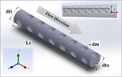
Figure 1. Schematic geometries of the tested model SSDT.
· The physical properties of the air at the annular diffuser inlet are constant.
· The flow properties are steady and incompressible.
· The wall temperature assumed to be constant at 870˚ K.
· The pressure at the diffuser outlet is set to Atmospheric.
· The velocity at the inlet boundary condition is 100 m/s.
· Inlet Reynolds number is (Re = 1.5 × 10⁴) based on the hydraulic diameter (Dh).
3. Computational Details
In the current study, three different diffuser wall angles (α) 1.8˚, 3.6˚ and 5.4˚ are evaluated via Computational Fluid Dynamics CFD by the commercial software ANSISY FLUENT 16.1.
3.1. Mesh Generation
For the present study, the computational domain for the model with three different diffuser wall angles α is formed by subtracting the annular diffuser section from the semi-dimpled tube section.
The structured grid generator ANSYS ICEM version 16.1 software is used to generate the grid arrangement for the annular diffuser and the SSDT. It is structured tetrahedral mesh generator software. It is designed to automatically generate meshes in complex 2D and 3D geometries.
3.2. Turbulence Model and Grid Generation
It is notably essential to pick the turbulence model for a specific simulation. The selected of the turbulence model is based upon two factors; first, the demands of the numerical analyses and second, the accuracy of the predicted flow phenomenon. The computational simulations are done in three-dimensional domains using the standard k-ε model as a turbulence model. Many researches obtained that the standard k-ε turbulence model can supply optimal performance for flows that have rotation, recirculation, and boundary layers effect [17] [18] . Therefore, it is adopted in the present work as a turbulence model to solve the computational analysis.
In order to accurate the numerical results, a grid independence study is performed to ensure that the results don’t depend on the grid quality. Thus, three different grid independence tests are carried out by utilized the grid systems with 96,735 elements, 105,803 elements and 112,535 elements at Reynolds number 1.5 × 10⁴ to evaluate the effects of grid sizes on the accuracy of the numerical solutions findings. The predicted temperature distribution for the various grid tests is compared. It is observed that the grid quality of 112,535 elements of the grid is selected for the simulation.
3.3. Governing Equations and Definitions
In this work, the steady incompressible Navier-Stokes equation is used to describe the temperature field and flow structure in an annular diffuser fitted with SSDT. These equations describe the conservation of mass, momentum, and energy for turbulent flows. In Cartesian tensor nations, the Navier-Stokes governing equations are as follows [16] [19] :
Continuity Equation
, (1)
Momentum Equation
, (2)
Energy Equation
, (3)
where, the quantity in Equation (2) represents the turbulent Reynolds stresses produced by velocity fluctuations . In addition, T is the temperature, 𝜌 is the density of the working fluid, λ is the thermal conductivity, and is the specific heat at a constant pressure.
3.4. The Numerical Results Validation
The numerical results are validated by simulating the temperature distribution of the airflow through the annular diffuser fitted with SSDT. The finding is compared with the reference experiment results from Ehan [16] as shown in Figure 2 and Table 1. From Figure 2 and Table 1, the finding reveals the accuracy of the numerical simulations results. The numerical simulation work agrees well with the experimental work. Thus, the largest differences for temperature are 0.1% and 0.04%, respectively as shown in Table 1.
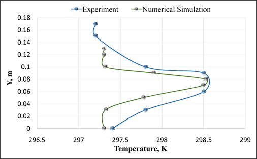
Figure 2. Temperature distribution validation with reference experiments data [16] .

Table 1. Validation data.
4. Results and Discussion
The numerical results of temperature field, pressure drop and flow structures of annular diffuser fitted with straight semi-dimpled tube SSDT are discussed in this part. The results are compared for three different α (1.8˚, 3.6˚ and 5.4˚).
4.1. Temperature Field Analysis
In this section, the effect of the straight semi-dimpled tube SSDT in the annular diffuser is displayed. The visualization of the temperature distribution contours is shown in Figure 3. The distribution of the temperature is tested for an outlet plane of the annular diffuser fitted to SSDT and three different diffuser wall angles α to be compared. Figure 3 shows that for the studied Reynolds number (Re) 1.5 × 10⁴, the temperature distribution decreases gradually with the increase of the diffuser wall angle α. This can be explained as the diffuser wall angle α increases, the outlet area of the annular diffuser increases, which results in a decrease of airflow recirculation and velocity. Consequently, the area of the distribution becomes smaller and limited.
The temperature distribution is plotted via the dimensionless value of Y\Di (the ratio of the radial flow direction and the annular diffuser inlet diameter) at Reynolds number (Re) 1.5 × 10⁴ and air temperature of 870˚ for different diffuser wall angles α of (1.8˚, 3.6˚ and 5.4˚), as shown in Figure 4. This figure displays that the distribution of the temperature is changed by a relatively small amount for the tested diffuser wall angles α in the radial direction of the airflow. Therefore, it can be noticed that the temperature values obtain at the diffuser wall angle α1 = 1.8˚ are slightly higher than those at α2 = 3.6˚ and α3 = 5.4˚. This is because that a higher diffuser wall angle α causes less tangential velocity components, resulting in a smaller distribution area. The corresponding enhancement in temperature distribution in the annular diffuser fitted with SSDT is about 0.8% and 4.2% for α2 and α3, respectively less than α1.
4.2. Flow Structure Analysis
The variation of the pressure drop distribution and the velocity distribution in the dimensionless radial airflow direction around a straight semi-dimpled tube is
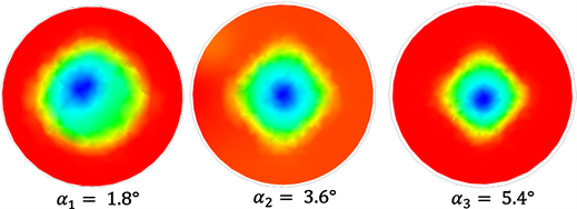
Figure 3. Visualization of the temperature distribution contours in an outlet plane for three different α of the annular diffuser fitted with SSDT.
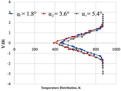
Figure 4. Temperature distribution in an outlet plane of the annular diffuser with SSDT for three different α.
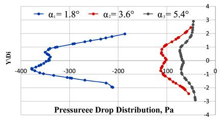
Figure 5. Pressure Drop distribution in an outlet plane of the annular diffuser with SSDT for three different α.
represented in Figure 5 and Figure 6, respectively.
The pressure drop field of different diffuser wall angles α is described in Figure 5. It can be seen that the pressure drop increases with the increases in the diffuser wall angle α. The results reveal that the diffuser wall angle (α3 = 5.4˚)

Figure 6. Velocity distribution in an outlet plane of the annular diffuser with SSDT for three different α.
provides a higher and better pressure drop than the tested diffuser wall angle α1 and α2 (1.8˚ and 3.6˚), respectively. Furthermore, the pressure drop increases by 108% and 136% for α2 and α3, respectively compared with α1. This pressure drop enhancement caused by the swirling flow because of air secondary flows. In the other hand, Figure 6 displays the velocity distribution in the outlet radial plane. The obtained results show that the velocity distribution profile decreases with the increases of diffuser wall angle α. This finding is because the use of SSDT with smaller diffuser wall angle α can cause swirling flow and pressure gradient in the radial direction. The velocity distribution increases because of increasing the radial swirl and pressure gradient through the flow direction. This can be attributed to the flow mixing behavior between the surface of the dimples and the wall surface of the annular diffuser. The swirling flow causes by small diffuser wall angle (α1 = 1.8˚) is stronger than that from using diffuser wall angles α2 and α3 (3.6˚ and 5.4˚), respectively. Thus, the velocity distribution in diffuser wall angles α2 and α3 recorded less enhancement about 26% and 53%, respectively.
5. Conclusions
A numerical study has been analyzed to investigate the temperature and flow field in an annular diffuser fitted with SSDT at Reynolds number (Re = 1.5 × 10⁴). Three different diffuser wall angles α (1.8˚, 3.6˚ and 5.4˚) are tested and simulated with air as the working fluid. From the numerical results, the conclusions are as follows:
1) Visualization technique is performed to display the effect of the SSDT insertions on the temperature field distribution in an outlet plane through the annular diffuser. It is observed that the temperature distribution is around 0.8% and 4.2% for diffuser wall angles α2 and α3, respectively and it is lower than that with diffuser wall angle α1. Thus, the diffuser wall angle (α1 = 1.8˚) recorded the best temperature distribution.
2) It is found that the larger diffuser wall angle α provides higher enhancement values of pressure drop around 108% and 136% for α2 and α3, respectively compared with the value of enhancement that provided by α1.
3) The velocity field finding indicates that the enhancement rate of the velocity distribution decreases as the diffuser wall angle α increases. The velocity distribution enhancement decreases by 26% for the diffuser wall angle α2 and 53% for the diffuser wall angle α3 in comparison with the diffuser wall angles α1.
Acknowledgements
The author would like to thank the Engineering Technical College-Baghdad, Middle Technical University MTU, Baghdad, Iraq for providing assistance and support for this research.
Conflicts of Interest
The authors declare no conflicts of interest regarding the publication of this paper.
Cite this paper
Askari, E.S.S. (2019) Design and Enhancement of Thermal Flow Characteristic in an Annular Diffuser under Turbulent Flow. Journal of Power and Energy Engineering, 7, 70-79. https://doi.org/10.4236/jpee.2019.79005
References
- 1. Rao, Y., Wan, C.Y. and Xu, Y.M. (2012) An Experimental Study of Pressure Loss and Heat Transfer in the Pin Fin-Dimple Channels with Various Dimple Depths. International Journal of Heat and Mass Transfer, 55, 6723-6733. https://doi.org/10.1016/j.ijheatmasstransfer.2012.06.081
- 2. Chimres, N., Wang, C.-C. and Wongwises, S. (2018) Optimal Design of the Semi-Dimple Vortex Generator in the Fin and Tube Heat Exchanger. International Journal of Heat and Mass Transfer, 120, 1173-1186. https://doi.org/10.1016/j.ijheatmasstransfer.2017.11.121
- 3. Xie, S., et al. (2018) Numerical Investigation on Heat Transfer Performance and Flow Characteristics in Enhanced Tube with Dimples and Protrusions. International Journal of Heat and Mass Transfer, 122, 602-613. https://doi.org/10.1016/j.ijheatmasstransfer.2018.01.106
- 4. Xie, S., Liang, Z., Zhang, L. and Wang, Y.L. (2018) A Numerical Study on Heat Transfer Enhancement and Flow Structure in Enhanced Tube with Cross Ellipsoidal Dimples. International Journal of Heat and Mass Transfer, 125, 434-444. https://doi.org/10.1016/j.ijheatmasstransfer.2018.04.106
- 5. Wang, S.T., et al. (2018) Flow Structure and Heat Transfer Characteristics of a Dimpled Wedge Channel with a Bleed Hole in Dimple at Different Orientations and Locations. International Journal of Heat and Mass Transfer, 117, 1216-1230. https://doi.org/10.1016/j.ijheatmasstransfer.2017.10.087
- 6. Zhang, F., Wang, X.J. and Li, J. (2017) Flow and Heat Transfer Characteristics in Rectangular Channels Using Combination of Convex-Dimples with Grooves. Applied Thermal Engineering, 113, 926-936. https://doi.org/10.1016/j.applthermaleng.2016.11.047
- 7. Qu, H.C., Shen, Z.Y. and Xie, Y.H. (2013) Numerical Investigation of Flow and Heat Transfer in a Dimpled Channel among Transitional Reynolds Numbers. Mathematical Problems in Engineering, 2013, Article ID: 989237. https://doi.org/10.1155/2013/989237
- 8. Tsynaeva and Nikitin (2016) Study of the Flow in a Channel with Dumbbell-Shaped Dimples. Procedia Engineering, 150, 2340-2344. https://doi.org/10.1016/j.proeng.2016.07.321
- 9. Binci, L., Clementi, G., D’Alessandro, V., Montelpare, S. and Ricci, R. (2017) Study of the Flow Field Past Dimpled Aerodynamic Surfaces: Numerical Simulation and Experimental. Journal of Physics: Conference Series, 923, Article ID: 012030. https://doi.org/10.1088/1742-6596/923/1/012030
- 10. Khalil, A.A. (2017) Turbulence Modelling of the Flow and Heat Transfer in Dimpled Channels. Ph.D. Thesis, University of Manchester, Faculty of Science and Engineering, Manchester.
- 11. Mihai, T. and Stevan, T. (2009) Optimal Design for the Interior Shape of a Annular Diffuser with Divergent Careening Considering the Minimum Whole Loss Pressure. UPB Scientific Bulletin, Series D, 71, 99-106.
- 12. Jason, D. (2009) On the Nature of the Flow in a Separated Annular. M.S. Thesis, College of Engineering and Computer Science, University of Central Florida, Orlando.
- 13. Mukesh, K.M. (2003) CFD Analysis of Fluid Flow through Equiangular Annular Diffuser. M.S. Thesis, Department of Mechanical Engineering, Delhi College of Engineering, University of Delhi, Delhi.
- 14. Pravin, P., Tushar, R., Mahesh, S., Akshay, J. and Taware, B. (2017) Experimental Study of Aerodynamics through a Conical Annulus and Axial Flow Runner. International Journal of Innovative Research in Technology, 3, 43-48.
- 15. Ehan, S.A. and Wirachman, W. (2018) Velocity and Pressure Analysis in a Divergent Area Fitted with Dimpled Hub. International Journal of Engineering & Technology, 7, 185-189.
- 16. Ehan, S.A. (2016) Numerical Analysis of Temperature Distribution Enhancement in Conical and Annular Diffuser Fitted with Swirl Generators. PhD Thesis, University Technology MARA, UiTM, Faculty of Mechanical Engineering, Shah Alam, Malaysia.
- 17. El Maakoul, A., Laknizi, A., Saadeddine, S., El Metoui, M., Zaite, A. and Meziane, M. (2016) Numerical Comparison of Shell-Side Performance for Shell and Tube Heat Exchangers with Trefoil-Hole, Helical and Segmental Baffles. Applied Thermal Engineering, 109, 175-185. https://doi.org/10.1016/j.applthermaleng.2016.08.067
- 18. Ehan, S.A., Basil, H.A. and Omer, M.M. (2017) Velocity Distribution in an Annular Diffuser Fitted with Twisted Hub for Different Area Ratios. Energy Procedia, 4th International Conference on Power and Energy Systems Engineering, Berlin, Vol. 141, 639-643. https://doi.org/10.1016/j.egypro.2017.11.086
- 19. Berge, D., Giat, M., Jean, R. and Rayan, R. (1995) Numerical Study of Turbulent Flow through Equiangular Annular Diffusers. Proceeding of 5th International Conference of Fluid Mechanics, Cairo, 2-5 January 1995, 719-729.