Smart Grid and Renewable Energy
Vol.10 No.05(2019), Article ID:92570,14 pages
10.4236/sgre.2019.105009
Simulating Annealing PLL for Autonomous Microgrid Systems
Ehab H. E. Bayoumi
Electrical and Electronics Engineering Department, University of Swaziland, Kwaulsini, Swaziland

Copyright © 2019 by author(s) and Scientific Research Publishing Inc.
This work is licensed under the Creative Commons Attribution International License (CC BY 4.0).
http://creativecommons.org/licenses/by/4.0/


Received: April 14, 2019; Accepted: May 20, 2019; Published: May 23, 2019
ABSTRACT
The Phase Locked Loop controller parameters are the key-point that affects the dynamic performance of the autonomous microgrid. They have to be optimally tuned to guarantee enhanced overall system stability. In this paper, two-microgrid plant with their associate PWM inverter connected to the ac main grid and the load is used as an example to demonstrate the capabilities of the proposed system. The Phase Locked Loop controller is designed and tuned using the Simulating Annealing algorithm. This algorithm is used to select the Phase Locked Loop PI controller gains with optimal percentage overshoot, rise time and settling time. The controller is tested during the transition between grid-connected and autonomous operation and in reverse order. The controller is compared with Ziegler and Nichols P and PI controllers. It shows the effectiveness and the extraordinary control response of the proposed control technique with respect to percentage overshoot, rise time and settling time control parameters compared to the conventional one.
Keywords:
Simulating Annealing, PI Controllers, Microgrid Operations

1. Introduction
Distributed generation (DG) resources are gaining a rapid growth connection to the utility grid, due to many factors including economics profits, environmental problems, global warming, gas emission, and tax encouragements [1]. Microgrids are reliable, due to their capability to island. It provides their customers with the power source to be supplied when the main ac grid is disconnected. Moreover, the microgrid should be adopted to be added to another microgrid sources and functions appropriately without any exceptional proposal [2]. Stability analysis for PWM-inverter microgrid is one of the apprehensions to function at the distribution level of the utility grid [3] [4] [5] [6] [7]. Although, active-power/frequency and reactive-power/voltage drop controls have been introduced to permit the microgrid sources to share power and preserve stability without the necessity for fast communications [1].
Phase locked loop (PLL) is used for synchronization [8]. There are some challenges in designing these PLLs. Some of them are: tuning the PLL gain parameters, its negative effects on the controller response, and coupling effects and interaction between itself and the system impedance [9] [10]. PLLs regularly engage a P or PI controller as the loop filter [11]. The classical controller has a limited potential to alleviate disturbance in PLL control loop which may exist due to a weak design or polluted grid. To develop the disturbance rejection ability of PLLs, cascading extra filters such as the moving average filter (MAF) [12] and the notch filters [13] may improve their functioning. But those filters diminish the dynamic performance of PLL as their target is to minimize their bandwidth. Another method is anticipated in [14] , which uses a lead compensator, an effective approach to obtain both high dynamic performance and excellent disturbance rejection. Adaptive Fuzzy is proposed in [15] to obtain fast and robust PLL system.
Evolutionary computations with stochastic search techniques assured to be a more brilliant method which affords a robust technique to resolve the controller parameters problem. The evolutionary computation for controller parameters identification is applied in many applications. Genetic algorithm (GA) is used to find out the controller parameters of the BLDC motor [16]. An evolutionary algorithm based on Particle Swarm Optimization (PSO) with weighting factors has been introduced for induction motor controllers’ parameters [17]. It should be noted that even the most successful nature-inspired optimization techniques, such as GA and PSO, are also sensitive to the increase of the problem difficulty and dimensionality, due to their stochastic type [18]. In previous years, more awareness is provided to bacterial foraging optimization (BFO) which has a powerful foundation for engineering applications. A few models have been achieved to signify bacterial foraging performances and use it for solving different challenges [19]. It solved these engineering challenges effectively.
In this paper, the simulating annealing (SA) technique is used to select the PLL PI-controller gains with a minimal percentage overshoot, rising time and settling time. These control parameters are having sensitive values that affect the dynamic performance of the autonomous microgrid. They have to be optimally adjusted to assure great improvement in the overall system stability. It organized as follows: Section 2 introduces the microgrid proposed system description. The problem formulation is given in Section 3. It includes inverter-main grid model, PLL model and system control methodology. In Section 4, the SA proposed technique is introduced. Results are given in Section 5. Finally, conclusions are presented in Section 6.
2. System Description
The overall block diagram for proposed autonomous microgrid system is given in Figure 1. It is consisting of two dc microgrids each is feeding a PWM inverter. Both are connected to the load and the main ac grid through transmission lines, transformers and circuit breaker. The two microgrids is connected to the main grid through circuit breaker, therefore it is certainly islanded by opening this circuit breaker (CB). In the islanding mode, the microgrids will continue serving the loads without any interruption. The two microgrids are able to resynchronize with the main grid when the islanding condition is cancelled.
3. Problem Formulation
The proposed control block diagram is shown in Figure 2. The idea is based on frequency and phase detection using the phase-locked loop (PLL) combined with the traditional control for active power to frequency drop and reactive power to voltage drop of the microgrid systems.
a) Inverter-main grid model
The inverter-main grid model is illustrated in Figure 3. The phase ac voltages at the terminal of the PWM inverter is and the terminal bus that is connected to the main ac grid is . Their phase angles are calculated with respect to the main grid sinusoidal waveform at the nominal frequency. The two busses are connected via a transformer and a transmission line, the overall impedance for them will .
b) Phase-locked loop model
The Block diagram for the PLL is illustrated in Figure 4. The concept is: the three-phase voltage (abc) are transformed into two phase-voltage (αβ) and then into two dc voltages (dq). The d-voltage component is the input to the PLL loop. The angle is the estimate output of the phase angle given by the PLL loop. The Vd can be expressed by:

Figure 1. The microgrid proposed system.

Figure 2. Block diagram for controlling the proposed system.

Figure 3. PWM Inverter-main grid model.

Figure 4. The PLL block diagram.
(1)
As is too small, Equation (1) can be rewritten:
(2)
The PLL frequency can be also expressed as:
(3)
The loop filter for the PLL can be represented either by a P [1] controller or PI controller [20].
c) System control methodology
The main control goals are to adjust the terminal bus voltage magnitude and the active power provided to the ac main grid PGen. The mathematical model describes the control idea of the autonomous microgrid system is given in [1]. Which can be summarized by the following equations and described in Figure 5:
(4)
where,
: the modulation index of the PWM inverter
: PWM inverter constant for integral control
: voltage constant follow a droop characteristic that is function on the grid power
: the phase angle difference between the inverter angle and the PLL angle
: active power constant for integral control
: active power depend on droop characteristic
: nominal active power output of the microgrid
: droop constant
: dc voltage output from the PWM inverter
: PWM inverter output current
: per-unit base voltage for the dc bus and PWM inverter
: per-unit base active power for the dc bus and PWM inverter
In [1] the mathematical model in Equation (4) is used and implemented as seen in Figure 5. The loop filter employed in method (1) was P-controller as illustrated in Figure 5. In the second method the loop filter used was PI-controller and the block diagram is simplified as shown in Figure 6 [20].
4. Proposed Control Technique
In Figure 6, there are two controllers one for the PLL and the other for the active power. A PI controller is used for the PLL loop, while a P controller is used for the active power loop. The gains for both controllers are tuned via evolutionary methods based on simulating annealing techniques. The tuned gains are guaranteed high-quality control responses for these controllers in regard of optimizing the control response parameters; minimum over-shot, rise-time and settling time control.

Figure 5. PLL and active power controllers block diagram, method (1) [1].

Figure 6. PLL and active power controllers block diagram, method (2) [20].
a) Simulating Annealing
Simulated Annealing (SA) is a straightforward efficient optimization technique presented in [21]. The function to be optimized in SA is called the energy, E(x), of the state x, and at the same point, the computational temperature (T), is dropped throughout the process. SA is an iterative trail algorithm that preserves a single candidate solution at any time [22]. Moreover, the main benefit of using SA is its capability to prevent being stuck in local optima. SA has been examined and showed a well performance in a variety of single-objective and multi-objective optimization application [23] [24].
The SA is used to optimize P and PI controller parameters of the active power and the PLL respectively. It is a multi-objective optimization problem as three step response parameters are simultaneously adjusted. In the proposed system, SA will accept a transition that leads to a decrease in all objectives (overshoot, rise time and settling time) or a decrease in one of the objectives if other objectives are not changed. SA will also accept a transition from state S1 to S2 if S2 does not dominate S1 with a probability of , where , and T is the temperature parameter which is being reduced over time during the process in order to decrease the possibility of accepting such transitions. The SA proposed approach for the PI-controller gains selection is summarized in flowchart shown in Figure 7.
5. Results
The microgrid proposed system in Figure 1 is used to demonstrate and test the dynamic behavior of the components of this system. All the ac quantities used in this system is articulated in per-unit values. The base values are given in Table 1.
In the proposed system, the set values for different elements are shown in Table 2.

Figure 7. The SA proposed approach for the PI-controller gains selection.

Table 1. Base value used in the proposed system.
Table 2. Set values of the proposed system.
The parameters of the two-PWM inverters and the PLL used in [1] are given Table 3. The controller parameters selected by SA is illustrated in Table 4.
The main test is implemented as given in [1] on the proposed system, the test scenario is as follows:
1) The CB connected to the grid is initially closed.
2) The two microgrids plants supply 1.3 pu of the active power demand by the load.
3) The remaining 0.4 pu active power is drawn from the main grid.
4) At t = 1 sec, the CB is opens and the total load has to be supplied by the two-microgrids plants.
5) At t = 7 sec, the CB is signaled to close, but closing is prevented until the voltage magnitude across the CB contacts reduces to the threshold pu3.
6) At t = 13.01 sec, the CB contacts are closed.
This test scenario is done for three PLL cases, case (1) is for PLL P-controller as in [1] and case two for PLL PI-controller designed by Ziegler and Nichols, and the proposed technique in case (3) is for PLL SAPI-controller in which the maximum overshot, rising time, and settling time parameters of the controlled parameter response is minimized.
Tuning the PLL controller parameters is a vital process in autonomous microgrid plants as it will reflects on many parameters response in these systems, as power, current and voltage. In this paper, the up given test scenario is done, and the results are given in Figures 8-11. Figure 8 shows the power delivered by each PWM inverters in the three-cases. In Figure 8(a) it shows the power delivered by the two plants, up is plant 1 and down is plant 2. Note that, Plant 1 has a higher set point than Plant 2. Therefore, the overshoot in Plant 1 for case (1) and case (2) is higher than in Plant 2 as shown in Figure 8(b) and Figure 8(c). Although, in the proposed technique (case (3)), the both plants have dead beat responses. Based on Figure 8 result, a comparison between overshoot, rise-time and settling-time parameters for the three-cases are given in Table 5. Based on this comparison the proposed technique case is the best compared to the other two cases.
Table 3. PWM inverters and PLL parameters.
Table 4. SA controllers’ parameters for PLL and active power.
Table 5. Control index-parameters comparison based on Figure 8.
The PLL frequency deviation for the two microgrid PWM inverters in the three cases is illustrated in Figure 9. The PLL SAPI-controller gives the best response from the three selected control parameters (percentage of maximum overshoot, rise time and settling time).
Moreover, the proposed technique in Figure 8, and Figure 9 are characterized by a deadbeat response which reflects the effectiveness realization of the proposed SAPI-controller designed in this paper.

Figure 8. Active Power output from the two microgrid PWM inverter plants during open and reclose of CB, (a) overall, (b) CB open, and (c) CB reclose.
Figure 10 presents the microgrid Plant 1 PWM inverter angle with respect to synchronous reference in the three cases. It also shows that the PLL angle strictly tracks the terminal bus angle. The differences between these quantities is provides obviously in Figure 11. It has been shown that the PLL SAPI-controller is the best and the fast to derive this difference to zero. Although, when the CB is closes, the subsequent phase shift in the PWM inverter terminal bus voltage
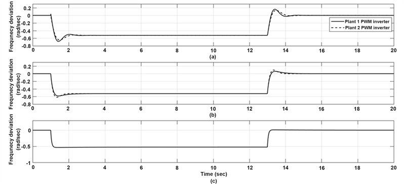
Figure 9. The PLL frequency deviation for the two microgrid PWM inverters in the three cases. (a) PLL P-controller, (b) PLL PI-controller, and (c) PLL SAPI-controller.

Figure 10. Microgrid Plant 1 PWM inverter angle with respect to synchronous reference in the three cases. (a) PLL P-controller, (b) PLL PI-controller, and (c) PLL SAPI-controller.
produces a spike in the angle difference across the PWM inverter and the transformer. That spike in angle difference is similar to spike in active power Pgen detected in Figure 8. In practice, the transformer inductance would limit most of these spikes.
6. Conclusions
Autonomous microgrid is being rapidly connected to the utility grid at the distribution level. For enhancing and improving the microgrid dynamic performance,
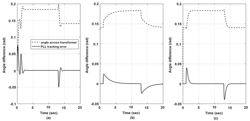
Figure 11. Microgrid Plant 1 PWM inverter angle differences in the three-cases. (a) for PLL P-controller, (b) for PLL PI-controller, and (c) for PLL SAPI-controller.
the active load needs to be synchronized with it. The phase locked loop (PLL) is used for this purpose. The main challenge in designing the PLL is tuning the gains for PLL active loop filter. In this paper, an example of two microgrids connected to the utility grid and the load is proposed. The dynamic model of the proposed system is given. The interaction between the dynamics of PWM inverter of any of the microgrid and the PLL can introduce oscillations. The gain selection of the PLL PI control is done by simulating annealing (SA) technique that granted minimal overshoot, rise time and settling time. The proposed PLL SAPI-controller provides and extraordinary response with these features. Results confirm the effectiveness of the proposed PLL controller to enrich the system dynamics and acts as a platform for autonomous microgrid systems.
Conflicts of Interest
The author declares no conflicts of interest regarding the publication of this paper.
Cite this paper
Bayoumi, E.H.E. (2019) Simulating Annealing PLL for Autonomous Microgrid Systems. Smart Grid and Renewable Energy, 10, 141-154. https://doi.org/10.4236/sgre.2019.105009
References
- 1. Hiskens, I.A. and Fleming, E.M. (2008) Control of Inverter-Connected Source in Autonomous Microgrids. American Control Conference, Seattle, 11-13 June 2008, 586-590. https://doi.org/10.1109/ACC.2008.4586555
- 2. Kroposki, B., et al. (2008) Making Microgrids Work. IEEE Power and Energy Magazine, 6, 40-53. https://doi.org/10.1109/MPE.2008.918718
- 3. Raju, E. and Jain, T. (2017) Robust Optimal Centralized Controller to Mitigate the Small Signal Instability in an Islanded Inverter Based Microgrid with Active and Passive Loads. International Journal of Electrical Power & Energy Systems, 90, 225-236. https://doi.org/10.1016/j.ijepes.2017.02.011
- 4. Han, H., Hou, X., Yang, J., Wu, J., Su, M. and Guerrero, J.M. (2016) Review of Power Sharing Control Strategies Forislanding Operation of AC Microgrids. IEEE Transactions on Smart Grid, 7, 200-215. https://doi.org/10.1109/TSG.2015.2434849
- 5. Chandorkar, M., Divan, D. and Adapa, R. (1993) Control of Parallel-Connected Inverters in Standalone AC Supply Systems. IEEE Transactions on Industry Applications, 29, 136-143. https://doi.org/10.1109/28.195899
- 6. Olivares, D., Mehrizi-Sani, A., Etemadi, A.H., Cañizares, C.A., Iravani, R., Kazerani, M., Hajimiragha, A.H., Gomis-Bellmunt, O., Saeedifard, M., Palma-Behnke, R., et al. (2014) Trends in Microgrid Control. IEEE Transactions on Smart Grid, 5, 1905-1919. https://doi.org/10.1109/TSG.2013.2295514
- 7. Tsikalakis, A. and Hatziargyriou, N. (2011) Centralized Control for Optimizing Microgrids Operation. Proceedings of the IEEE Power and Energy Society General Meeting, San Diego, 24-29 July 2011, 1-8. https://doi.org/10.1109/PES.2011.6039737
- 8. Hassan, M.A., Worku, M.Y. and Abido, M.A. (2018) Optimal Design and Real Time Implementation of Autonomous Microgrid Including Active Load. Energies Journal, 11, 1109. https://doi.org/10.3390/en11051109
- 9. Dong, D., Wen, B., Boroyevich, D., Mattavelli, P. and Xue, Y. (2015) Analysis of Phase-Locked Loop Low-Frequency Stability in Three-Phase Grid-Connected Power Converters Considering Impedance Interactions. IEEE Transactions on Industrial Electronics, 62, 310-321. https://doi.org/10.1109/TIE.2014.2334665
- 10. Svensson, J. (2001) Synchronization Methods for Grid-Connected Voltage Source Converters. IEEE Proceedings of Generation Transmission and Distribution, 148, 229-235. https://doi.org/10.1049/ip-gtd:20010101
- 11. Golestan, S., Monfared, M., Freijedo, F. and Guerrero, J. (2013) Advantages and Challenges of a Type-3 PLL. IEEE Transactions on Power Electronics, 28, 4985-4997. https://doi.org/10.1109/TPEL.2013.2240317
- 12. Golestan, S., Ramezani, M., Guerrero, J.M., Freijedo, F.D. and Monfared, M. (2014) Moving Average Filter Based Phase-Locked Loops: Performance Analysis and Design Guidelines. IEEE Transactions on Power Electronics, 29, 2750-2763. https://doi.org/10.1109/TPEL.2013.2273461
- 13. Espin, F.G., Figueres, E. and Garcera, G. (2012) An Adaptive Synchronous Reference-Frame Phase-Locked Loop for Power Quality Improvement in a Polluted Utility Grid. IEEE Transactions on Industrial Electronics, 59, 2718-2731. https://doi.org/10.1109/TIE.2011.2166236
- 14. Freijedo, F.D., Yepes, A.G., Lopez, O., Vidal, A. and Gondoy, J.D. (2011) Three Phase PLLs with Fast Postfault Retracking and Steady-State Rejection of Voltage Unbalance and Harmonics by Means of Lead Compensation. IEEE Transactions on Power Electronics, 26, 85-97. https://doi.org/10.1109/TPEL.2010.2051818
- 15. Hamed, H.A., Abdou, A.F., El-Kholy, E.E. and Bayoumi, E.H.E. (2016) Adaptive Cascaded Delayed Signal Cancelation PLL Based Fuzzy Controller under Grid Disturbances. IEEE 59th International Midwest Symposium on Circuits and Systems, Abu Dhabi, 16-19 October 2016, 1-4. https://doi.org/10.1109/MWSCAS.2016.7870061
- 16. Xia, C., Guo, P., Shi, T. and Wang, M. (2004) Speed Control of Brushless DC Motor Using Genetic Algorithm Based Fuzzy Controller. 2004 International Conference on Intelligent Mechatronics and Automation, Chengdu, 26-31 August 2004.
- 17. Bayoumi, E.H.E. and Soliman, H.M. (2007) PID/PI Tuning for Minimal Overshoot of Permanent-Magnet Brushless DC Motor Drive Using Particle Swarm Optimization. Electromotion Scientific Journal, 14, 198-208.
- 18. Kennedy, J. and Eberhart, R.C. (2001) Swarm Intelligence. Morgan Kaufmann, San Francisco.
- 19. Bayoumi, E.H.E. (2010) Parameter Estimation of Cage Induction Motors Using Cooperative Bacteria Foraging Optimization. Electromotion Scientific Journal, 17, 247-260.
- 20. Surprenant, M., Hiskens, I. and Venkataramanan, G. (2011) Phase Locked Loop Control of Inverters in a Microgrid. IEEE Energy Conversion Congress and Exposition, Phoenix, 17-22 September 2011, 667-672. https://doi.org/10.1109/ECCE.2011.6063833
- 21. Kirkpatrick, S., Gelatt Jr., C.D. and Vecchi, M.P. (1983) Optimization by Simulated Annealing. Sciences Journal, 220, 671-680. https://doi.org/10.1126/science.220.4598.671
- 22. Vega-Rodriguez, M.A., Gomez-Pulido, J.A., Alba, E., Vega-Perez, D., Priem-Mendes, S. and Molina, G. (2007) Evaluation of Different Metaheuristics Solving the RND Problem. Workshops on Applications of Evolutionary Computation, Valencia, 11-13 April 2007, 101-110. https://doi.org/10.1007/978-3-540-71805-5_11
- 23. Jaraiz-Simon, M.D., Gomez-Pulido, J.A., Vega-Rodriguez, M.A. and Sanchez-Perez, J.M. (2013) Simulated Annealing for Real-Time Vertical-Handoff in Wireless Networks. International Work-Conference on Artificial Neural Networks, Tenerife, 12-14 June 2003, 198-209. https://doi.org/10.1007/978-3-642-38679-4_19
- 24. Huang, K.-Y. and Hsieh, Y.-H. (2011) Very Fast Simulated Annealing for Pattern Detection and Seismic Applications. IEEE International Geoscience and Remote Sensing Symposium, Vancouver, 24-29 July 2011, 499-502. https://doi.org/10.1109/IGARSS.2011.6049174