Open Journal of Fluid Dynamics
Vol.09 No.03(2019), Article ID:94361,17 pages
10.4236/ojfd.2019.93014
Volume Flow Rate Optimization of an Axial Fan by Artificial Neural Network and Genetic Algorithm
Yingkun Zhang, Yu Wang, Tao Liu, Jingyin Li
School of Energy and Power Engineering, Xi’an Jiaotong University, Xi’an, China

Copyright © 2019 by author(s) and Scientific Research Publishing Inc.
This work is licensed under the Creative Commons Attribution International License (CC BY 4.0).
http://creativecommons.org/licenses/by/4.0/


Received: July 10, 2019; Accepted: August 12, 2019; Published: August 15, 2019
ABSTRACT
The present study is to improve the volume flow rate of an axial fan through optimizing the blade shape under the demand for a specified static pressure. Fourteen design variables were selected to control the blade camber lines and the stacking line and the values of these variables were determined by using the experimental design method of the Latin Hypercube Sampling (LHS) to generate forty designs. The optimization was carried out using the genetic algorithm (GA) coupled with the artificial neural network (ANN) to increase the volume flow rate of the axial fan under the constraint of a specific motor power and a required static pressure. Differences in the aerodynamic performance and the flow characteristics between the original model and the optimal model were analyzed in detail. The results showed that the volume flow rate of the optimal model increased by 33%. The chord length, the installation angle and the cascade turning angle changed considerably. The forward leaned blade was beneficial to improve the volume flow rate of the axial fan. The axial velocity distribution and the static pressure distribution on the blade surface were improved after optimization.
Keywords:
Axial Fan, Volume Flow Rate, Genetic Algorithm, Artificial Neural Network

1. Introduction
The axial fan, is widely used in the industrial process. It plays an important role in ventilation due to its high flow rate and compact size. Nowadays, the axial fan is facing an increasing demand for high aerodynamic performance and different requirements.
The rapid development of the computational fluid dynamics (CFD) makes it possible to analyze the flow characteristics of the axial fan in detail and to study the influence of various parameters on the fan performance. Many researchers have studied the aerodynamic performance of axial fans by using CFD approaches. For example, Sarraf et al. [1] investigated the effect of blade thickness on the performance of axial fans and their results showed that the efficiency of the fan with thick blades was lower than that of the thin blade fan but the thick blade fan had a wider operation range. Li et al. [2] explored the influence of blade angles on the performance of an axial fan and found that an abnormal blade angle due to the deformation of the blade would deteriorate aerodynamic performance and increase the noise of the fan. Moreover, abnormal blade angles would result in an obviously disturbed distribution of the total pressure along the blade. Liu et al. [3] studied the influence of the uneven circumferential blade space on the performance of the axial fan and their results indicated that the optimal unequally spaced fan would decrease the discrete noise at the near field monitoring point. Zhu et al. [4] applied the splitter blade to the axial fan and found that splitter blades could improve the static pressure of the axial fan and decrease the pressure pulsation on the surface of the main blades. Further, Li et al. [5] investigated the influence of the chord length of splitter blades on the performance of the axial fan and their results showed that splitter blades with an appropriate chord length would have a certain effect on enhancing the static characteristics and improving the aerodynamic noise characteristics. Zhang et al. [6] investigated the effects of convex grooves on the blade pressure surface and the wave-shaped trailing edge on the performance of an axial fan. Their results indicated that the convex grooves on the blade pressure surface changed the turbulent structures near the wall, and the wave-shaped trailing edge changed the flow direction of vortex shedding, which would reduce the influence of vortex shedding on the far-field region. Yang et al. [7] analyzed the influence of the blade perforation on the internal flow field and aerodynamic noise characteristics. The results showed that the perforated blades improved the flow in the axial fan and reduced the pressure pulsation amplitude caused by the turbulence of the blade surface boundary layer. Jung et al. [8] investigated the effect of the fairing geometry on the efficiency of the axial fan and showed the efficiency was improved with aspecific fairing length, because the flow separation near the fairing was reduced.
The influence of the blade tip clearance on the flow characteristics of the fan also attracts the researchers’ interests. For instance, Pogorelov et al. [9] paid attention on the impact of the tip clearance on the time-averaged and the instantaneous flow field of the axial fan and found that a reduction of the tip clearance decreased the shifting amplitude of the tip vortex. Ye et al. [10] proposed five blade tip shapes and studied their effects on the performance of the axial fan. Results showed that the leakage flow rate was reduced evidently and the mixing losses between the leakage flow and the main stream were decreased with the grooved blade tip. Moghadam et al. [11] analyzed the tip-leakage flow in an axial fan. The results showed that increasing the tipsize enlarged the diameter and the strength of the main tip vortex and decreased the efficiency of the fan. Lee et al. [12] investigated the evolution of tip-leakage vortex in a low-pressure axial flow fan using digital particle image velocimetry and found that the evolution of the vortex in downstream was highly influenced by the incoming flow rate.
The axial fan blade is usually composed of different sectional airfoils along the spanwise direction. Therefore, many studies also focused on the stacking line of the blade. For example, Nazmi et al. [13] investigated the influence of the stacking line on the performance of the axial fan and the results revealed that the forward and the backward swept blade do not significantly affect the overall performance of the fan at the design flow rate. However, at low flow rates, the forward and backward swept blades have positive and negative effects on the fan performance, respectively. Kromer et al. [14] compared the influence of the unskewed, forward skewed and backward skewed blades on the performance of the axial fan and reported that the forward skewed fan had the best aerodynamic performance over a broad operating range.
Optimization of the turbomachinery has been made much progress with the aid of CFD techniques in the past decades and has found wide applications in practice. Kim et al. [15] optimized the hub-to-tip ratio, hub cap installation distance, hub cap ratio, and the stagger angles at the mid-span and tip of an axial fan through a hybrid multi-objective evolutionary algorithm (MOEA) coupled with a response surface approximation (RSA) surrogate model. Kim et al. [16] improved the total efficiency of an axial fan through optimizing six variables defining the blade lean angle and the blade profiles using the Non-dominated Sorting of Genetic Algorithm (NSGA-II) coupled with the response surface approximation (RSA) surrogate model. Song et al. [17] optimized the blade sectional profiles and the stacking line utilizing an improved cooperative co-evolution algorithm (CCEA) optimizer and one-stage Expected Improvement (EI) based adaptively updated Kriging surrogate model.
However, the above studies mainly concentrated on improving the efficiency of the axial fan at design point through optimization. In many cases, it is necessary to maximize the volume flow rate under the constraint of the motor power. The purpose of this paper is to increase the volume flow rate of an axial fan through optimizing the blade shape under the constraint of the motor power. The original axial fan model and the numerical simulation pre-setting were introduced in Section 2. The geometry parameterization in Section 3 was achieved by NUMECA Software. Fourteen design variables were selected to control the blade camber lines and the stacking line. Forty designs were generated in the design space using the experimental design method of the Latin Hypercube Sampling (LHS) and the optimization was conducted using the genetic algorithm (GA) coupled with the artificial neural network (ANN). The blade shape changed obviously after optimization. The results showed that the volume flow rate of the axial fan increased by 33% under the constraint of the motor power of 865 W. The axial velocity distribution and the static pressure distribution of the optimal blade were improved significantly. The power capacity of the mid-span section of the optimized blade increased evidently. In addition, the static pressure efficiency of the axial fan also increased at different volume flow rates.
2. Geometric Model and Numerical Method
2.1. Geometric Model
The original geometric model used in this paper is an axial fan with a diameter of 48 inches (1219.2 mm) as shown in Figure 1. It has three blades with a rotational speed of 550 rpm. The specification of the axial fan is presented in Table 1.
2.2. Numerical Simulation Pre-Setting
The Reynolds-averaged Navier-Stokes equations (RANS) and the Spalart-Allmaras turbulence model were employed to simulate the flow in the axial fan. The simulations were conducted by using the NUMECA Software, and the post-processing was carried out by using the CFView Software. The configuration of the fan is presented in Figure 2. The hub was extended to the inlet and the outlet boundary of the axial fan.
A single passage of the axial fan was adopted as the computational domain in this paper to reduce the computation load. The grid distribution of the axial fan impeller is presented in Figure 3. The minimum grid orthogonality is greater than 22.88˚, the maximum aspect ratio is less than 4487 and the maximum expansion ratio is less than 2.76, which meet the NUMECA’s requirements for the grid quality ( orthogonality > 10˚, aspect ratio < 5000, expansion ratio < 5). The inlet and outlet boundary conditions are given as follows: the total pressure is specified at inlet and the static pressure is given at outlet. Actually, the outlet static pressure is set to 0 Pa and the inlet total pressure is set to −25 Pa. In this design, the demanded static pressure of the fan, defined as the difference between the outlet static pressure and the inlet total pressure as shown in Equation (1), is 25 Pa. The fan static pressure efficiency is defined by Equation (2) and the power is calculated according to Equation (3). The rotational speed of the blade is 550 rpm and the periodic boundary condition is employed for the single flow

Figure 1. General view of the original model.

Figure 2. Configuration of the original axial fan.

Figure 3. Grid distribution of the blade.

Table 1. Design parameters of the original axial fan model.
passage. The working fluid is set as the air, the incompressible fluid flow solver is adopted and the density keeps 1.2 kg/m3. No-slip wall and adiabatic conditions are applied to the blade, hub and shroud surface. The numerical simulation is considered to be convergent when the residual is less than 10−6. Grid-independence validation is carried out based on the volume flow rate obtained from the above boundary conditions. As shown in Figure 4, the volume flow rate of the axial fan is almost unchanged when the grid number is greater than 1,860,000, which can be considered that the grid independence solutions are obtained. In the following simulations, the grid number of the axial fan is set to 1,860,000 to ensure a reliable result.
(1)
(2)
(3)
where Pst is the fan static pressure, Pst−2 is the static pressure at the outlet, Pt−1 is the total pressure at the inlet, ηst is the fan static pressure efficiency, Q is the volume flow rate, N is the power, T is the torque and (rad/s) is the rotational speed.
3. Optimization Method
3.1. Geometric Parameterization and Design Variables
The parameterization of the original model fan is essential to the optimization cost. In this paper, the hub and the shroud of the fan are parameterized by straight lines. Three sections, i.e., the 0% (hub), 50% and 100% (shroud) span sections are selected to parameterize the blade of the original axial fan, as shown in Figure 5. The three sectional blade profiles are represented by the camber line and the thickness distribution. The camber line in each section is parameterized by four variables, as shown in Figure 6. In Figure 6, δ1 is the angle between the chord and the camber tangent line at the blade leading edge, δ2 is the angle between the chord and the camber tangent line at the blade trailing edge, γ is the angle between the chord and the rotating axis and Chord is the length of the blade chord. The thickness distribution is parameterized by the three-order Bezier curves. For the axial fan, the leaned direction is the circumferential direction of the blade, while the swept direction moves along the rotating axis. The lean of the blade sectional profiles is parameterized using the simple Bezier curve with two variables, β1 and β2, and the blade sweep is parameterized using the simple Bezier curve with β3 andβ4, as shown in Figure 7. The stacking point of the sectional profiles is the gravity center of the sectional airfoils. The above parameterizations are implemented by using the Autoblade module in NUMECA.
In this paper, the camber lines of the three parameterized sections (the 0%, 50% and 100% sections) and the lean of the blade are optimized while the blade thickness distribution and the sweep characteristics remain unchanged. In total, fourteen design variables are selected to optimize the blade shape and the values of these variables are presented in Table 2. The symbols, S1, S2 and S3, represent the 0%, 50% and 100% span sections, respectively.

Figure 4. Grid-independence validation of the original model.

Figure 5. Stacking sections.

Figure 6. Camber line parameterization.
3.2. Optimization Objective
In this paper, the goal of the optimization is to increase the volume flow rate of the axial fan as high as possible under the constraint of the power of 865 W, which is the maximum power the motor can provide. The volume flow rate and the power are obtained using the above grid distribution and boundary conditions in Section 2.

Figure 7. Lean and sweep representations. (a) Lean; (b) Sweep.
Table 2. Values of the design variables.
3.3. Optimization Procedure
The artificial neural network (ANN) is used to construct the approximate model. An ANN is composed of several elementary processing units called nodes. These nodes are arranged in layers and joined with connections of different intensity, called connection weight, in order to form a parallel architecture. A network is generally composed of several layers: an input layer, one or several hidden-layers and an output layer. Pairs of input/output vectors must be available in a training database that the network will learn to predict. Trained networks tend to give reasonable answers to inputs that they have never seen. Therefore, it is possible to train a network on a representative set of input/output pairs and get good results without training the network on all possible input/output pairs.
Genetic algorithm (GA) mimics the natural behavior in terms of biological evolution in order to reach the best possible solution to a given problem. An initial population is generated and pairs of individuals are selected from this population based on their performances. Weak individuals tend to die before reproducing while stronger ones live longer and bear many offspring.
The overall optimization procedure in this paper is shown in Figure 8. In detail, forty samples are selected using LHS in the design space and analyzed by CFD simulations at the initial stage. Then ANN is constructed using the evaluated samples, which is then used to replace the computationally-expensive CFD codes. In the successive steps, GA is employed to predict the optimal geometry, which would be analyzed by the CFD simulation and added to the original database. After that, ANN is constructed again using the new samples. The accuracy of ANN would be improved due to the more samples using GA. This process would be iterated until the terminated condition is satisfied, i.e. the prescribed upper limit of design iterations or the expected performance improvement is achieved. The number of layers for the present ANN is 2, the population size of this GA is 50 and the number of the design iterations is 40.
4. Results and Discussion
4.1. Comparison of the Original Model and the Optimal Model
The spanwise blade profiles for both the original model and the optimal model are compared in Figure 9. At the 0% section, the blade profile changes slightly. At 50% span, both the blade angle and the chord length increase significantly. Further, the blade angle and the chord length decrease at the 100% span. The specific parameters of the original and the optimal models are presented in Table 3. In Table 3, θ is defined as the cascade turning angle, which is equal to the sum of absolute values of δ1 and δ2. The ratio in Table 3 is calculated according to the Equation (4), which means the relative changes of the optimal model with reference to the original model.
(4)
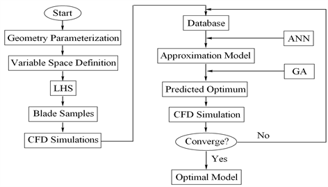
Figure 8. Overall optimization procedure.

Figure 9. Comparison of the spanwise blade profiles. (a) 0% span section; (b) 50% span Section; (c) 100% span section.
Table 3. Comparison of the design variables.
It can be noted that the differences in chord lengths at 50% span and 100% span are significant. The relative changes of the two sections are more than 10%. The variation of the blade angle at 50% span is more than 16%, which is much larger than the other two sections. In addition, the cascade turning angles at 0% span and 50% increase obviously. However, for the 100% span section, the cascade turning angle decreases significantly.
The meridional views of the two models are presented in Figure 10. The difference between the two models is noticable. In addition, the blade of the

Figure 10. Meridionalviews.(a) Original model; (b) Optimal model.
original model is straight, which means that the blade is stacked along the radial direction. However, the forward leaned blade is obtained after optimization, as shown in Figure 11, which shows the obvious lean along the circumferential direction.
4.2. Aerodynamic Performance Analysis
In order to show the improvement effect of the optimization, the aerodynamic performances of the original model and the optimal model were simulated using the same grid and boundary conditions. The numerical results are presented in Figure 12. In Figure 12, the static pressure and the static pressure efficiency are defined by Equations (1) and (2), respectively. It can be seen that the volume flow rate of the optimal model increases obviously at the same fan static pressure. Especially, at the design static pressure of 25 Pa, the volume flow rate increases from 24,727.2 m3/h to 33,002.0 m3/h. In addition, the static pressure efficiency of the optimal model is higher than that of the original model at different volume flow rates.
4.3. Flow Characteristics Analysis
As mentioned above, the volume flow rate at the fan static pressure of 25 Pa increases from 24,727.2 m3/h to 33,002.0 m3/h after optimization and the power of the optimal fan is 857.95 W, which is satisfied with the optimization goal. The flow characteristics of the original and optimal models at the design point (Pst = 25 Pa) are analyzed in detail.
The axial velocity distribution at meridional plane for both the original and optimal models are presented in Figure 13. It can be seen that there are obvious differences between the two models. The inlet axial velocity of the optimal model is generally higher than that of the original model. At outlets, the low-velocity regions appear near the hub for both models. However, for the optimal model, the low-velocity regions are much smaller. Additionally, the axial velocity at middle span of the optimal model is much higher and the high-velocity regions become larger, which would help to increase the volume flow rate.

Figure 11. Diagram of the original model and the optimal model.
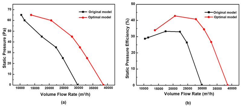
Figure 12. Aerodynamic performances of the original model and the optimal model. (a) Static pressure; (b) Static pressure efficiency.

Figure 13. Axial velocity contours at meridional plane. (a) Original model; (b) Optimal model.
In order to compare the outlet axial velocity of the two models carefully, the axial velocity at Z = 140 mm is presented in Figure 14. As can be seen in Figure 14, the axial velocities at 0% - 10% span for both models are similar and less than zero, which means there is backflow near the hub. At 10% - 90% span, the axial velocities of the optimal model are much higher than those of the original model. Moreover, at 30% - 80% span, the axial velocity gradients along the spanwise of the optimal model decrease obviously, which would improve the flow field and reduce the flow losses. In addition, the axial velocity at 90% - 100% span of the optimal model is smaller than that of the original model, which would decrease the tip leakage flow rate. It can be concluded that the average axial velocity of the optimal velocity increases and the axial velocity distribution becomes reasonable, which would be beneficial to increase the volume flow rate of the axial fan.
The static pressures and the total pressures at both the plane of Z = −20 mm and the plane of Z = 140 mm, which are just at the upstream and downstream of the blade of the two models respectively, are presented in Figure 15. It can be seen that the optimal blade inlet static pressure is lower than the original blade inlet. The static pressure rise of the optimal model is obviously higher than the original model, especially at 50% - 80% span. The outlet total pressure of the optimal blade is also higher than the original blade, which results in the higher total pressure rise of the optimal model. It demonstrates that the aerodynamic performance of the optimal model is improved obviously.
Figure 16 shows the static pressure distribution on the blade surface at 10%, 50% and 90% spans. The magnitude of the static pressure represents the force acting on the blade surface. The area enclosed by the curves represents the power capacity of the blade. As can be seen from Figure 16, the power capacities of the optimal blade at the hub and midspansections become stronger than the

Figure 14. Axial velocity at Z = 140 mm.

Figure 15. Pressure distribution along the spanwise. (a) Static pressure; (b) Total pressure.

Figure 16. Static pressure distributions on blade surfaces. (a) 0% span; (b) 50% span; (c) 90% span.
original blade, while the power capacity at the tip section changes a little. In addtion, it is known that the slope of the pressure curve indicates the gradient of the static pressure on the blade surface. The favorable pressure gradient is beneficial to the flow on the blade surface, while the adverse pressure gradient would cause the flow separation and deteriorate the flow. From Figure 16, it can be seen that the favorable pressure gradient on the pressure surface of the three sections of the optimal blade increases, which would improve the load distribution on the blade surface. Moreover, the static pressure gradient on the suction surface decreases more uniformly.
5. Conclusions
The optimization of an axial fan was performed by the genetic algorithm coupled with the artificial neural network. Fourteen design variables were selected to define the camber lines of sectional airfoils and the stacking line of the blade. The main conclusions are summarized as follows:
1) The optimization method adopted in this paper is effective to increase the volume flow rate at the specified static pressure of an axial fan. In this paper, the volume flow rate of the optimized fan at the static pressure of 25 Pa increases by 33% compared with the initial designed (the original) fan with a constraint on the power.
2) The chord length, the installation angle and the cascade turning angle have obvious effects on the volume flow rate of the axial fan. In detail, the chord lengths at 50% span and 100% span, the blade installation angle at 50% span and the cascade turning angle at 100% span change significantly after optimization.
3) The axial velocity distribution becomes more uniform after optimization. The power capacity of the mid-span section of the optimized blade increases evidently. In addition, the static pressure distribution on the blade surface becomes more reasonable.
Acknowledgements
This work was financially supported by the National Key R & D Program of China (2018YFB0606101) and the Natural Science Foundation of China (51876158 and 51776145).
Conflicts of Interest
The authors declare no conflicts of interest regarding the publication of this paper.
Cite this paper
Zhang, Y.K., Wang, Y., Liu, T. and Li, J.Y. (2019) Volume Flow Rate Optimization of an Axial Fan by Artificial Neural Network and Genetic Algorithm. Open Journal of Fluid Dynamics, 9, 207-223. https://doi.org/10.4236/ojfd.2019.93014
References
- 1. Sarraf, C., Nouri, H., Ravelet, F. and Bakir, F. (2011) Experimental Study of Blade Thickness Effects on the Overall and Local Performances of a Controlled Vortex Designed Axial-Flow Fan. Experimental Thermal and Fluid Science, 35, 684-693. https://doi.org/10.1016/j.expthermflusci.2011.01.002
- 2. Li, C.X., Lin, Q., Ding, X.L. and Ye, X.M. (2016) Performance, Aeroacoustics and Feature Extraction of an Axial Flow Fan with Abnormal Blade Angle. Energy, 103, 322-339. https://doi.org/10.1016/j.energy.2016.02.147
- 3. Liu, Y., Lin, Z., Lin P.F., Jin, Y.Z., Setoguchi, T. and Kim, H.D. (2016) Effect of the Uneven Circumferential Blade Space on the Performance of Small Axial Flow Fan. Journal of Thermal Science, 25, 492-500. https://doi.org/10.1007/s11630-016-0890-7
- 4. Zhu, L.F., Jin, Y.Z., Li, Y., Jin, Y.Z., Wang, Y.P. and Zhang, L. (2013) Numerical and Experimental Study on Aerodynamic Performance of Small Axial Flow Fan with Splitter Blades. Journal of Thermal Science, 22, 333-339. https://doi.org/10.1007/s11630-013-0632-z
- 5. Li, G.Q., Zhu, L.F., Hu, Y.J., Jin, Y.Z., Setoguchi, T. and Kim, H.D. (2015) Influence of Chord Lengths of Splitter Blades on Performance of Small Axial Flow Fan. Open Mechanical Engineering Journal, 9, 361-370. https://doi.org/10.2174/1874155X01509010361
- 6. Zhang, L., Jin, Y.Z. and Jin, Y.Z. (2013) An Investigation on the Effects of Irregular Airfoils on the Aerodynamic Performance of Small Axial Flow Fans. Journal of Mechanical Science and Technology, 27, 1677-1685. https://doi.org/10.1007/s12206-013-0416-0
- 7. Yang, X.L., Wu, C.H., Wen, H.B. and Zhang, L.L. (2018) Numerical Simulation and Experimental Research on the Aerodynamic Performance of Large Marine Axial Flow Fan with a Perforated Blade. Journal of Low Frequency Noise, Vibration & Active Control, 37, 410-421. https://doi.org/10.1177/0263092317714697
- 8. Jung, J.H. and Joo, W.G. (2019) The Effect of the Entrance Hub Geometry on the Efficiency in an Axial Flow Fan. International Journal of Refrigeration, 101, 90-97. https://doi.org/10.1016/j.ijrefrig.2019.02.026
- 9. Pogorelov, A., Meinke, M. and Schröder, W. (2016) Effects of Tip-Gap Width on the Flow Field in an Axial Fan. International Journal of Heat and Fluid Flow, 61, 466-481. https://doi.org/10.1016/j.ijheatfluidflow.2016.06.009
- 10. Ye, X.M., Zhang, J.K. and Li, C.X. (2017) Effect of Blade Tip Pattern on Performance of a Twin-Stage Variable-Pitch Axial Fan. Energy, 126, 535-563. https://doi.org/10.1016/j.energy.2017.03.057
- 11. Moghadam, S.M.A., Meinke, M. and Schröder, W. (2019) Analysis of Tip-Leakage Flow in an Axial Fan at Varying Tip-Gap Sizes and Operating Conditions. Computers and Fluids, 183, 107-129. https://doi.org/10.1016/j.compfluid.2019.01.014
- 12. Lee, H.K., Park, K.T. and Choi, H. (2019) Experimental Investigation of Tip-Leakage Flow in an Axial Flow Fan at Various Flow Rates. Journal of Mechanical Science & Technology, 33, 1271-1278. https://doi.org/10.1007/s12206-019-0227-z
- 13. Nazmi, L.A. and Ayder, E. (2014) Influence of the Sweep Stacking on the Performance of an Axial Fan. Engineering Applications of Computational Fluid Mechanics, 8, 518-529. https://doi.org/10.1080/19942060.2014.11083304
- 14. Krömer, F.J., Moreau, S. and Becker, S. (2019) Experimental Investigation of the Interplay between the Sound Field and the Flow Field in Skewed Low-Pressure Axial Fans. Journal of Sound and Vibration, 442, 220-236. https://doi.org/10.1016/j.jsv.2018.10.058
- 15. Kim, J.H., Kim, J.W. and Kim, K.Y. (2011) Axial-Flow Ventilation Fan Design through Multi-Objective Optimization to Enhance Aerodynamic Performance. Journal of Fluids Engineering, 133, Article ID: 101101. https://doi.org/10.1115/1.4004906
- 16. Kim, J.H., Choi, J.H., Husain, A. and Kim, K.Y. (2010) Performance Enhancement of Axial Fan Blade through Multi-Objective Optimization Techniques. Journal of Mechanical Science and Technology, 24, 2059-2066. https://doi.org/10.1007/s12206-010-0619-6
- 17. Song, P. and Sun J.J. (2015) Blade Shape Optimization for Transonic Axial Flow Fan. Journal of Mechanical Science and Technology, 29, 931-938. https://doi.org/10.1007/s12206-015-0207-x