Effect of Melt Scan Rate on Microstructure and Macrostructure for Electron Beam Melting of Ti-6Al-4V ()
1. Introduction
Laser and electron beam processing of metal and alloy powders using CAD-driven scanning strategies to selectively heat and melt additive layers forming 3D components can be considered a new directional solidification approach [1-4]. In these processes, the focused laser or electron beam is scanned over a prepared powder bed to pre-heat the bed prior to a final melt scan or melt-scan sequence. The selection of scan parameters such as energy density in the focal region or beam current in the case of electron beam melting (EBM), and scan speed and beam scan spacing create local and spatially connected melt pools which produce columnar solidification regimes. These regimes provide the thermo-kinetics for microstructure development and propogation, often with each melted layer providing an epitaxial platform which ideally can produce directionally oriented (textured) columnar (or elongated) grains and related columnar microstructures [3,4].
Thijs et al. [4] recently discussed the influence of scanning strategy and scan parameters on aspects of microstructural evolution of Ti-6Al-4V during selective laser melting (SLM) where the scan speed varied from 50 mm·s−1 to 200 mm·s−1. These scan speeds produced primarily α¢-martensite (hcp, a = 0.293 nm; c = 0.468 nm) platelets in contrast to acicular α (hcp, a = 0.295; c = 0.466) phase grains characteristic of conventional cast or wrought Ti-6Al-4V products, and EBM-fabricated Ti- 6Al-4V products [5]. In addition, and because of variations in cooling rate with scan speed, the α¢-martensite size regime decreased, resulting in a hardness increase from HV (Vickers microindentation hardness) 409 to 479, or 4.1 GPa to 4.8 GPa, respectively. Higher scan speeds and reduced scan spacing also produced notable porosity as a consequence of unmelted powder regions [4].
In the present study, we examined porosity development and microstructure variations in Ti-6Al-4V with systematic changes of EBM scan speeds, ranging from 100 mm·s−1 to 1000 mm·s−1; while maintaining a constant beam current in the melt scan phase. Light optical microscopy (LOM) and scanning and transmission electron microscopy (SEM and TEM, respectively) were used to characterize the microstructure variations, while corresponding microindentation and macroindentation hardnesses were measured utilizing Vickers hardness (HV) and Rockwell C-scale hardness (HRC) measurements, respectively. Tensile testing was also performed in selected cases.
2. Materials and Methods
In this research, an Arcam A2 electron beam melting (EBM) system shown schematically in Figure 1 was
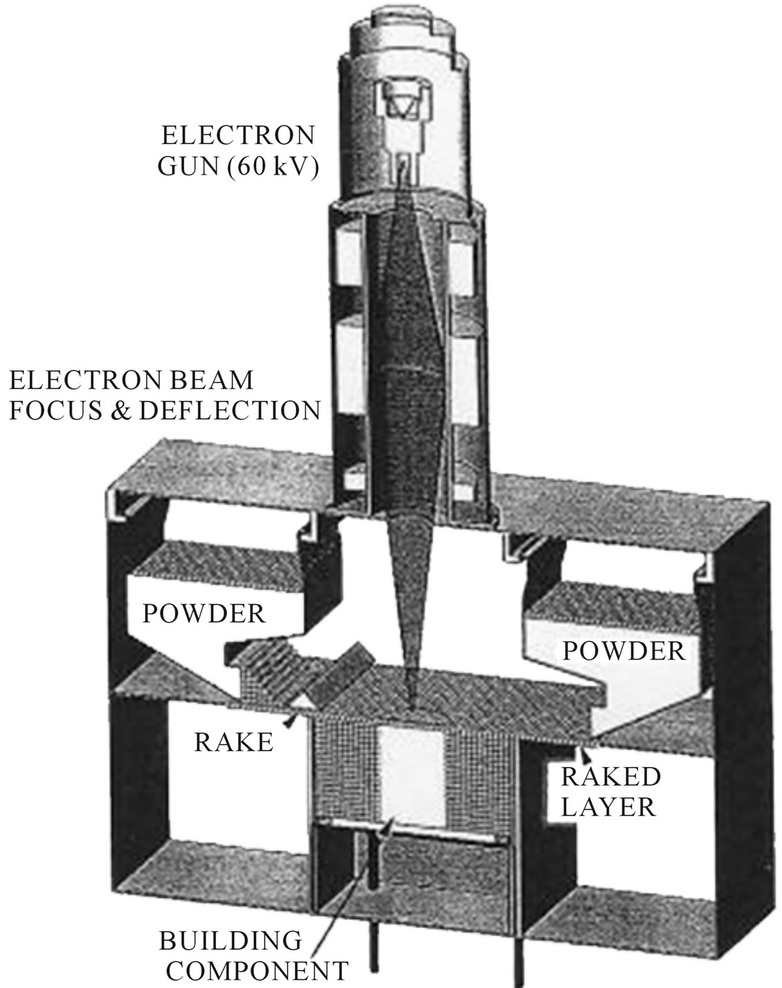
Figure 1. Arcam A2 EBM system schematic.
used to fabricate Ti-6Al-4V test cylinders measuring 2 cm in diameter and 8 cm in length. These cylinders were built in both a vertical orientation (with the cylinder axis parallel to the z-axis build direction) and a horizontal (with the cylinder axis perpendicular to the build direction or in the x-y powder layer plane) orientation. Figure 2 shows the build model for these test specimen orientations. The Ti-6Al-4V powder (nominally 6.2% Al, 3.6% V, 0.13% O; average powder diameter of 30 µm) was gravity fed from cassettes shown in Figure 1 onto the build table where it was raked into a layer roughly 3 particle diameters thick. This raked layer was preheated (to ~650˚C) by scanning the electron beam at speeds of ~104 mm/s in multiple scans (~11) at ~30 mA beam current, using an accelerating voltage of 60 kV. The system vacuum was >10−4 Torr, while a He gas bleed in the build area reduced the vacuum but improved build component cooling. During the melt scan following the preheat scanning, the beam current was reduced to 6 mA. Melt scan rates in this study included 100, 400, 500, 600, 700, and 1000 mm·s−1. The beam focus and scan spacing were maintained at a constant value during the cylindrical specimen fabrication illustrated in Figure 2.
Disc sections were cut from the vertical (z-axis) built cylinders perpendicular to the build direction along the cylinder axis while rectangular sections were cut parallel to the horizontal cylinder axes, and perpendicular to the build direction. These sections were ground, polished,
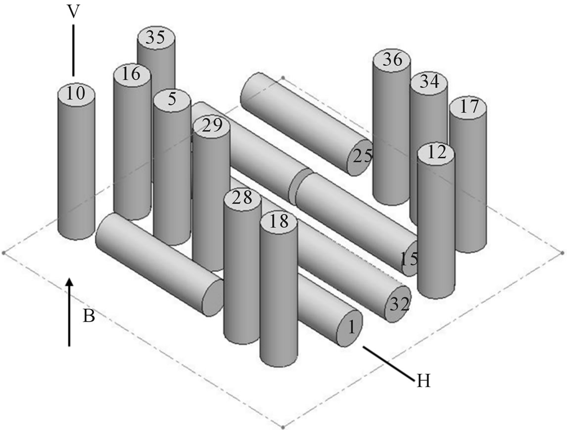
Figure 2. Isometric CAD model representing vertical (V) and horizontal (H) build orientations. The build direction is represented by arrow denoted B.
and etched with a Kroll reagent consisting of 0.1 L water, 5 mL nitric acid and 2.5 mL hydrofluoric acid for about 3 s. Thin slices were also prepared from these specimen sections and ground to 0.2 mm thicknesses from which 3 mm discs were punched in order to prepare TEM specimens using a dual-jet electropolishing system and an electrolyte consisting of 0.9 L methanol to which 50 mL sulfuric acid was added. Electropolishing was performed at −10˚C at 15 - 25 volts.
For LOM observations, we employed a Reichert MEF4 A/M metallograph with a digital imaging system. Samples prepared for LOM by etching were also observed directly in the SEM (A Hitachi S-4800 field-emission SEM) operated at 20 kV in the secondary electron emission mode. The SEM was also fitted with an energydispersive (X-ray) spectrometer system for elemental analysis. Specimens for TEM were observed in a highresolution, Hitachi H-9500 TEM operated at 300 kV, employing a goniometer-tilt stage.
The specimen sections cut from the vertical and horizontal-built cylindrical components illustrated in Figure 2 for LOM were also used for macro and micro-hardness testing. Rockwell-C-scale macrohardness was measured using a 1.5 kN load, while digital Vickers microindentation hardness was measured using a 100 gf (0.1 N) load. Macrohardness (HRC) was averaged from a minimum of 10 indentations per sample, while microhardness (HV) in units of GPa was averaged from a minimum of 10 indentations, representing 20 diagonals.
Representative horizontal and vertical cylinders built in arrays as shown in Figure 2 were also machined into standard tensile specimens for tensile testing at room temperature (20˚C) using a strain rate of 2 × 10⁻³·s−1. These tests were averaged from 3 specimens in both the vertical and horizontal build orientations (Figure 2) for each build corresponding to the melt scan rates noted earlier. This was true for macro and micro-indentation hardness testing as well.
For samples prepared at each melt-scan as modeled in Figure 2, the density was measured and compared with ideal, fully dense Ti-6Al-4V (having a density rs of 4.42 g/cm3) as relative density: r/rs. The corresponding porosity (in percent) was then obtained from (1 – r/rs) 100.
3. Results and Discussion
Table 1 provides a summary matrix for this experimental study and illustrates generally that as the melt scan rate increased for the EBM fabrication of vertically or horizontally built cylinders, the Young’s modulus (or stiffness) decreased along with the tensile properties and macrohardness (HRC), corresponding to an increase in residual porosity. The notable variance in Table 1 was the increase in microhardness (HV) with increasing porosity for the horizontal built cylinders compared to the vertical built cylinders were the values increased then decreased. This contrast in macrohardness and microhardness is due to the response of the Rockwell indenter to porosity, while the Vickers indenter responded almost exclusively to microstructural variations which occurred in response to the melt scan rate change. It can be recalled that the Rockwell indenter represents a load of 1.5 kN while the Vickers indenter represents a load of only 0.1 N. Consequently, the macrostructure is being influenced by increasing porosity and correspondingly by microstructural changes in acicular α grain size and related phenomena.