Hard-to-Soft Transition in Radial Buckling of Multi-Concentric Nanocylinders ()
1. Introduction
The term “buckling” refers to a deformation through which a pressurized material undergoes a sudden failure and exhibits a large displacement in a direction transverse to the load [1]. A typical example of buckling occurs when pressing opposite edges of a long, thin elastic beam toward one another. For small loads, the beam is compressed in the axial direction while keeping its linear shape and the strain energy is proportional to the square of the axial displacement. Beyond a certain critical load, however, it suddenly bends into an arc shape and the strain energy and displacements are no longer related by a quadratic expression. Besides axial compression, bending and torsion give rise to buckling of elastic objects, where the buckled patterns depend strongly on the geometric and material parameters.
An interesting class of elastic buckling can be observed in structural pipe-in-pipe cross sections under hydrostatic pressure [2,3]. Pipe-in-pipe (i.e., a pipe inserted inside another pipe) applications are commonly used in offshore oil and gas production systems in civil engineering. In subsea pipelines in deep water, for instance, buckling resistance to huge external hydrostatic pressure is a key structural design requirement. Pipe-inpipe systems may be an efficient design solution that meets this strict requirement, because their concentric structures enable the cross section to withstand high pressure without collapsing.
The above argument regarding macroscopic objects poses a question as to what buckling behavior may be observed in nanometer-scale (10–9 m) counterpart objects. In nanomaterial sciences, the buckling of carbon-based hollow cylinders with nanometric diameters (called carbon nanotubes) has drawn great attention [4]. Extensive studies on carbon nanotube mechanics have been thus far driven by their exceptional resilience against deformation; that is, the recovery of the original cylindrical shapes of the carbon nanotubes upon unloading, even when subjected to severe loading conditions. In addition to the excellent strain-relaxation reversibility, carbon nanotubes exhibit high fatigue resistance; therefore, they are a promising medium for the storage of mechanical energy with an extremely high energy density [5]. Nevertheless, due to their nanometric scales, the similarities and differences in the buckling patterns compared with those of their macroscopic counterparts are not trivial. This complexity has motivated tremendous efforts toward the analysis of the buckling of carbon nanotubes under diverse loading conditions: axial compression [6-10], radial compression [11-22], bending [23-28], torsion [29-32], and combinations of these [33].
In this article, we focus our attention on the radial buckling of carbon nanotubes observed under hydrostatic pressure on the order of several hundreds of megapascal. Thin-shell-theory based analysis on the cross-sectional deformation of nanotubes leads us to the conclusion that the buckled patterns strongly depend on the inter-tube separation , the number of constituent tubes
 , and the innermost tube diameter
 . In particular, the expansion of
  from its equilibrium value (0.34 nm) causes a lowering of the critical tube number
  that characterizes the hard-to-soft transition in the nanotubes’ radial buckling. These results shed light on the possible control of the morphology of carbon nanotubes by experimentally tuning
 .
.
2. What Are “Carbon Nanotubes”?
Carbon nanotubes are one of the most promising nanomaterials, and they consist of layers of graphene sheets that are each a single atom thick (two-dimensional hexagonal lattices of carbon atoms) rolled up into concentric cylinders [34]. By convention, they are categorized as single-walled nanotubes (SWNTs) or multi-walled nanotubes (MWNTs): the former is made by wrapping one single layer into one seamless cylinder, while the latter comprise two or more concentric graphitic tubes. The constituent tubes in MWNTs are coupled to one another via the van der Waals (vdW) interaction, wherein the separation between adjacent concentric tubes is approximately 0.34 nm in equilibrium conditions.
The excellent mechanical properties of carbon nanotubes are characterized by the remarkably high Young’s modulus, which is on the order of terapascal (i.e., several times stiffer than steel), and the tensile strength, which is as high as tens of gigapascal [33]. These properties are proof that carbon nanotubes are the stiffest and strongest materials on earth. In addition to the marked stiffness, carbon nanotubes exhibit astounding flexibility when subjected to external hydrostatic pressure. The radial deformation both of SWNTs and MWNTs is an important consequence of this flexibility; however, the theoretical understanding of the flexibility of MWNTs is still lacking due to their structural complexity.
Emphasis should be placed on the fact that on application of a mechanical deformation, carbon nanotubes show significant changes in their physical and chemical properties [34,35]. Precise knowledge of their deformation mechanism and available geometry is, therefore, crucial for understanding their structure-property relations and for developing next generation carbon-nanotube-based applications.
3. Formulation
3.1. Continuum Approximation
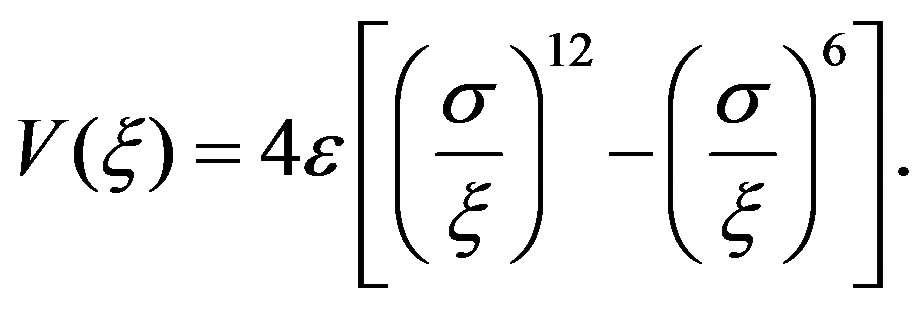
The aim of this section is to deduce the stable cross-sectional shape of a MWNT under a hydrostatic pressure . The continuum elastic approximation [36- 41] allows the mechanical energy
  of a MWNT per axial length to be expressed as follows:
 (1)
(1)
Here,  is the deformation energy of all concentric tubes,
  is the interaction energy of all adjacent pairs of tubes, and
  is the potential energy of the applied pressure. All these three energy terms are functions of
  and the deformation amplitudes
  and
and  that describe the radial
  and circumferential
  displacements, respectively, of the
  th tube. See Equation (7) below for the precise definitions of
  and
and .
.
The optimal displacements  and
and  that minimize
  under a given
  are obtained via the calculus of variations to
  with respect to
  and
and . To proceed, we derive the explicit forms of
 ,
,  , and
, and  as functions of
 ,
,  , and
, and  in the subsequent section.
3.2. Strain-Displacement Relation
Evaluating the functional form of  requires the relation between the displacements,
  and
and , and the circumferential strain,
  , of a hollow tube driven by cross-sectional deformation. Suppose there is a circumferential line element of length1
  lying at an arbitrary point within the cross section of a tube with thickness
 . The hydrostatic pressure
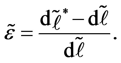
  upon the tube causes an extensional strain
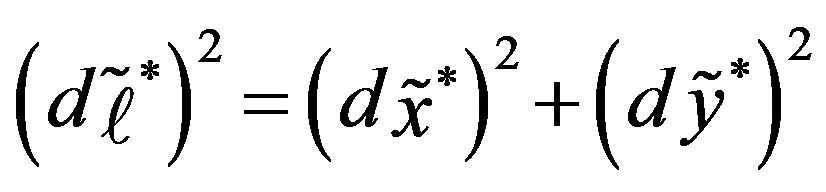
  of the line element, which is defined as follows:
 (2)
(2)
Here,  , and
, and  is the length of the line element after deformation (the asterisk symbolizes the quantity after deformation). The coordinates
 ,
,  of the element after deformation are given as follows:
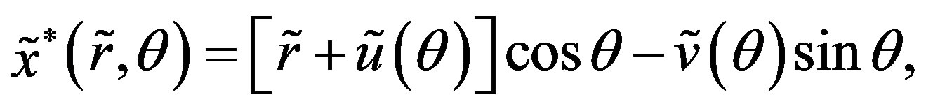 (3)
(3)
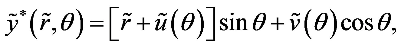 (4)
(4)
where  and
and  are the components of the displacement vector in the radial and circumferential directions, respectively. We can then write the following relationships:
 , (5)
, (5)
the following relationship can be obtained:
 (6)
(6)
where , etc. The term
  in Equation (6) accounts for the rotation of the line element due to the deformation [16]. The formula (6) is valid for an arbitrarily large rotation,
 .
.
Hereafter, we assume that  and
and  are both significantly smaller than unity, because an infinitesimal deflection of the initially circular cross section is assumed to determine the critical buckling pressure. The second term in the right side in Equation (6) can therefore be omitted if the possibility that
  or
or  is larger than
  is excluded. We further assume that the normals to the undeformed centroidal circle
  of the hollow tube’s cross section remain straight, normal, and unextended during the deformation [16]. The second assumption means that within each cross section, neither shear deformation nor thickness modulation arises in the circumferential direction; this leads to the following expressions:
 (7)
(7)
where  and
and  denote the displacements of a point that lies on
 , and
, and  is a radial coordinate measured from
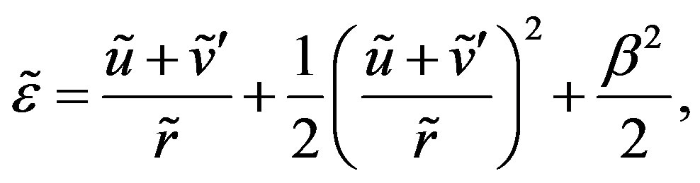
 . By substituting Equation (7) into Equation (6), we can derive the following strain-displacement relationship:
 (8)
(8)
where the following definitions hold true:
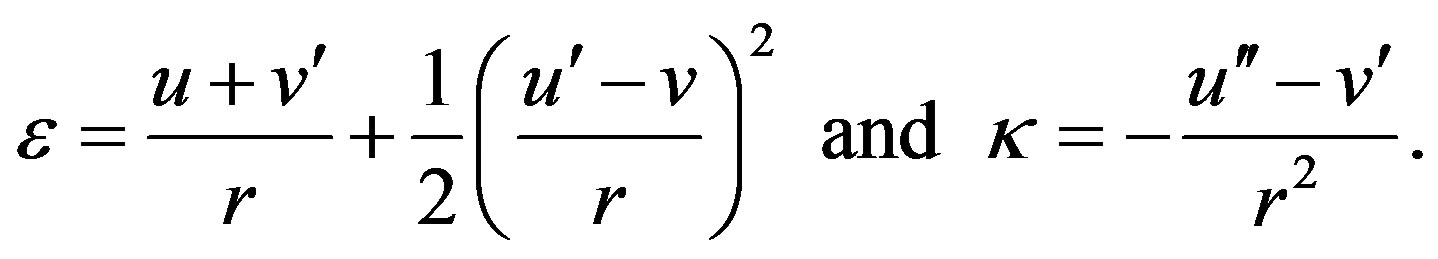 (9)
(9)
Here,  and
and  are the in-plane and bending strains, respectively, of the
  th tube;
  is the radius of the undeformed circle
 . Equations (8) and (9) state that the circumferential strain at an arbitrary point in the cross section is determined by the displacements
  and
and  of a point that lies on the undeformed centroidal circle
 .
.
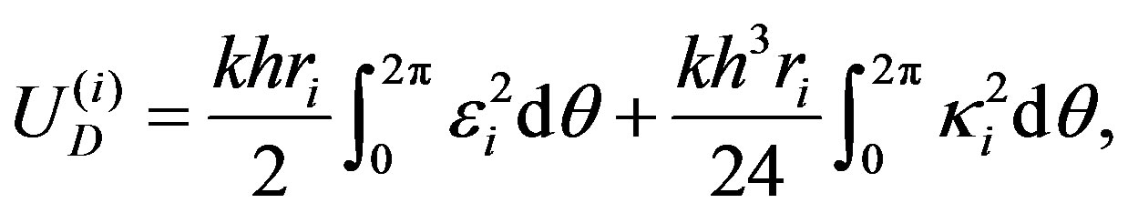
3.3. Deformation Energy
We are now ready to derive the explicit form of the deformation energy . Suppose that the
  th constituent tube has a thickness
 . A surface element of the crosssection of the hollow tube can then be expressed by
 . The stiffness
  of the surface element for stretching along the circumferential direction is given as follows:
 (10)
(10)
where  and
and  are the Young’s modulus and Poisson’s ratio, respectively, of the tube. Thus, the deformation energy
  per axial length can be written as follows:
 (11)
(11)
in which the component  associated with the
  th tube is written as follows:
 (12)
(12)
From Equations (8) and (12) we obtain the following relationship:
 (13)
(13)
which can also be written as follows:
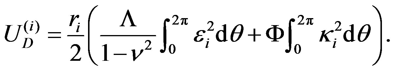 (14)
(14)
The constant  denotes the in-plane stiffness,
  the flexural rigidity, and
  the Poisson ratio of each tube.
For quantitative discussions, the values of  and
and  must be carefully determined. In cases of macroscopic objects, they are defined as
  and
and
 . However, for carbon nanotubesthe macroscopic relations for
  and
and  noted above fail because there is no unique way of defining the thickness of the graphene tube [42]2 Thus, the values of
  and
and  should be evaluated ab-initio from direct measurements or through computations involving the properties of carbon sheets, without reference to the macroscopic relations. In actual calculations, we substitute
  nN/nm,
  nN·nm, and
  in a similar fashion as a previous study [43] based on the density functional theory.
3.4. Inter-Tube Coupling Energy
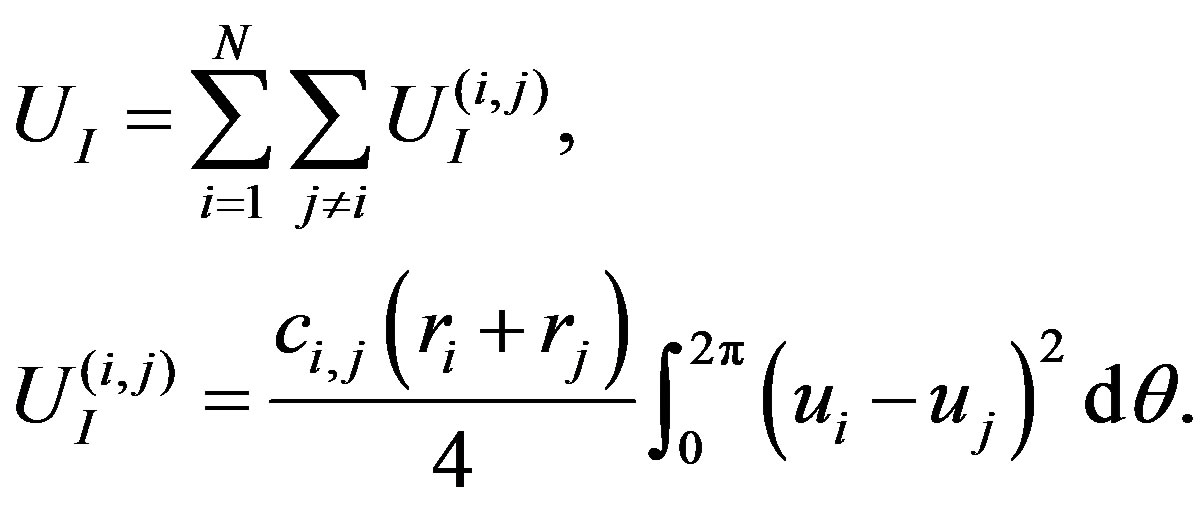
The energy associated with the van der Waals (vdW) interaction between adjacent pairs of tubes, designated by  in Equation (1), can be written as a sum of components as follows:
 (15)
(15)
We derive the coefficients  in Equation (15) through a first order Taylor approximation of the vdW pressure [39,44] associated with the vdW potential as follows:
 (16)
(16)
Here,  is the distance between a pair of carbon atoms,
  nm is the equilibrium distance between two interacting atoms, and
  nN·nm is the well depth of the potential [45]. The resulting equilibrium spacing between neighboring tubes is 0.3415 nm. The derivative
  represents the force between two carbon atoms, and its surface integral provides the inter-wall pressure induced by the vdW coupling.
The vdW pressures on the inner and outer tubes of a concentric two-walled tube with radii  and
and  are given as follows [44] (with positive signs for compression):
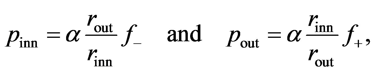 (17)
(17)
where . The area density of carbon atoms is given by
  nm–2.
nm–2.
 (18)
(18)
In Equation (18),  ,
,  ,
,
 , and
, and , and
, and
 .
.
In the following, we obtain analytical expressions for  by linearizing the Equation (17) for the pressure [22]. Note that
  depends quadratically on the change in spacing between two adjacent tubes. Consider two consecutive tubes with radii
  and
and , where the subscripts
  and
and  correspond to
  and
and , respectively. The vdW energy stored due to a perturbation
  along the positive direction of pressure is given as follows:
 (19)
(19)
where  is the mean radius and
  is the vdW pressure on the
  th tube. The corresponding linearized pressure is given by
 . In Equation
(19),  describes the length of the infinitesimal element on which the pressure is acting. Using the linearized pressure and comparing with Equation (15), the following expressions for the vdW coefficients can be found:
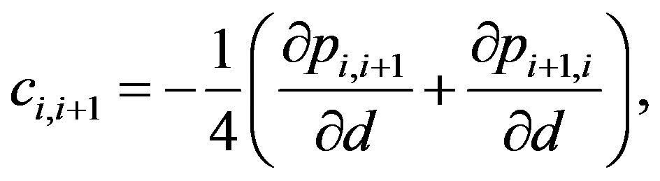 (20)
(20)
where the derivatives in Equation (20) are defined as follows:
 (21)
(21)
Note that  is symmetric. The set of Equations (15), (20), and (21) allows for the evaluation of
 .
.
3.5. Pressure-Induced Energy
We finally derive an explicit form of , which is the negative of the work done by the external pressure
  during cross-sectional deformation. Using this definition we can write the following expression:
 (22)
(22)
where  is the area surrounded by the
  th tube after deformation (the sign of
  is assumed to be positive inward).
  can then be obtained by evaluating the following expression:
 (23)
(23)
By substituting Equations (3) and (4) into Equation (23), and by using the periodicity relation , the following expression can be obtained:
 (24)
(24)
3.6. Critical Pressure Evaluation
This section presents our method for determining the critical pressure  above which the circular cross section of MWNTs is elastically deformed into a noncircular one. To carry out this analysis, we decompose the radial displacement terms according to
  . Here,
  indicates a uniform radial contraction of the
  th tube at
 , whose magnitude is proportional to
 .
.  describes a deformed, non-circular cross section observed just above
 . Similarly, we can write
 , because
  at
at .
.
By applying the variational method to  with respect to
  and
and , we obtain the following system of 2N linear differential equations:
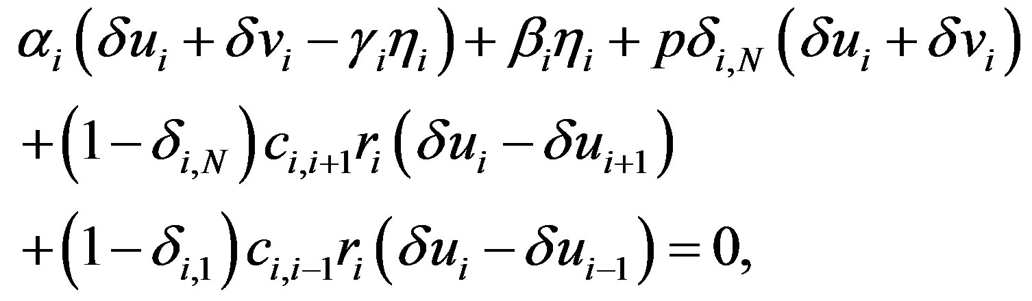 (25)
(25)
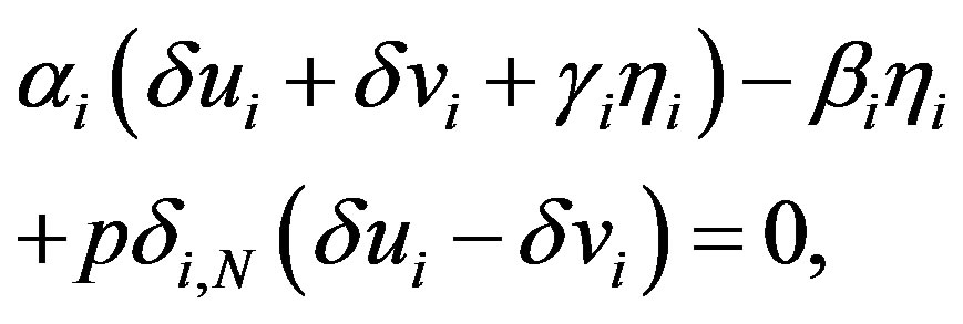 (26)
(26)
where  and
and . In deriving Equations (25) and (26), the quadratic and cubic terms in
  and
and  are omitted because we only consider elastic deformation with sufficiently small displacements. In addition, the terms consisting only of
  and
and  are also omitted; the sum of such terms should be equal to zero3 because
  represents an equilibrium circular cross-section under
 .
.
Because  and
and  are periodic in
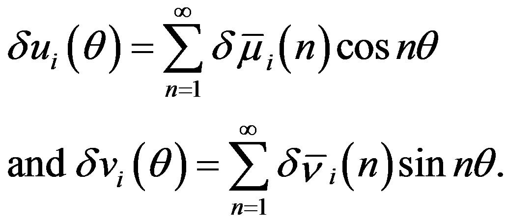
 , the general solutions of Equations (25) and (26) are given by the Fourier series expansions as follows:
Substituting these into Equations (25) and (26) leads to the matrix equation , in which the vector
  consists of
  and
and  with all possible
  and
and , and the matrix
  involves one variable
  as well as parameters such as
  and
and . The matrix
  can be expressed as a block diagonal matrix of the form
 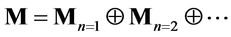 due to the orthogonality of
  and
and . Here,
  is a
is a  submatrix that satisfies
 , where
  is a 2N-column vector composed of
  and
and  . As a result, the secular equation
  that provides nontrivial solutions of Equations (25) and (26) can be rewritten as follows:
 (27)
(27)
By solving Equation (27) with respect to , we obtain a sequence of discrete values of
 . Each of these values is the smallest solution of
 . The minimum of these values serves as the critical pressure
  that is associated with a specific integer
 . From the definition, the
  associated with a specific m allows only
  and
and  to be finite, however, it also requires
  and
and . Immediately above
 , therefore, the circular cross section of MWNTs becomes radially deformed as follows:
 (28)
(28)
where the value of  is uniquely determined by the one-to-one relation between
  and
and .
.
4. Result and Discussion
4.1. Critical Pressure Curve
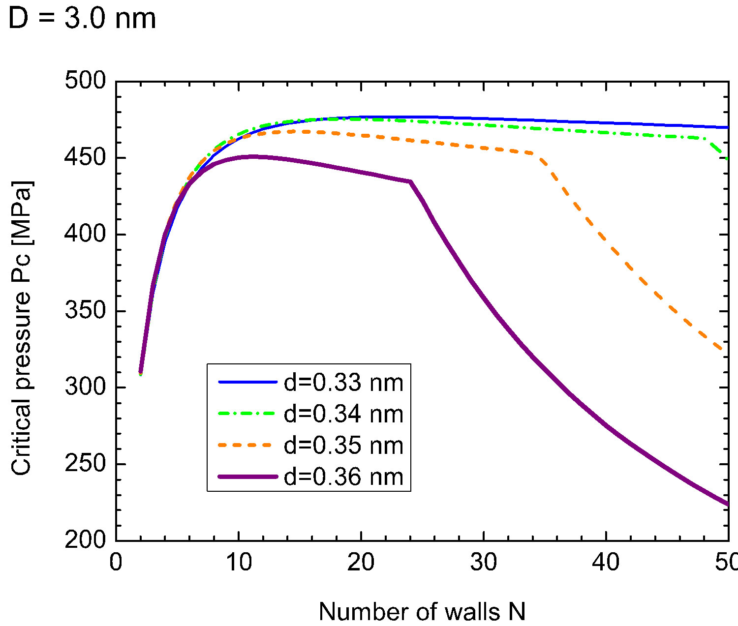
Figures 1(a) and (b) show  as a function of
  for various values of the initial tube-tube separation
  prior to the application of pressure. For all
 , we observe a rapid increase in
  with
with , which is followed by a slow decay when
  nm (and also for smaller D).4 The increase in
  for small
  is interpreted as the “hardening” of the MWNTs, i.e., an enhancement of the radial stiffness of the entire MWNT by encapsulation. This hardening effect disappears with a further increase in
 , which results in the decay of
 . A decay in
  implies that a relatively low pressure suffices to produce a radial deformation, which indicates an effective “softening” of the MWNT. These two contrasting effects, i.e., hardening and softening, are both due to the encapsulation of MWNTs.
| 4Such a decay is also observed for D = 5.0 nm and larger D, in principle, if a sufficiently large N is considered [but omitted in Figure 1(b)]. |
We emphasize that in Figure 1(a), the softening region (i.e.,  -decay region) is enlarged by expanding the inter-tube distance
  prior to deformation. As will be confirmed later, this tendency agrees with the existing numerical simulations that were based on a coarsegrained model of MWNTs [21]. The variation of
  is thought to be feasible in MWNT synthesis. During synthesis, the interlayer thermal contraction upon cooling and/or the intertube adhesion energy owing to the increased intertube commensuration may result in a deviation in
  from the equilibrium value [46,47].
4.2. Sequential Change in Buckling Modes
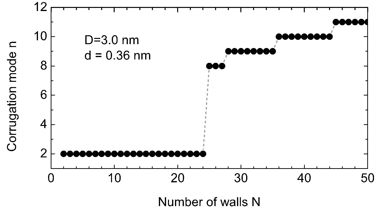
Figure 2 provides (a) the index  of deformation modes and (b)-(g) the cross-sectional views observed just
 (a)
(a)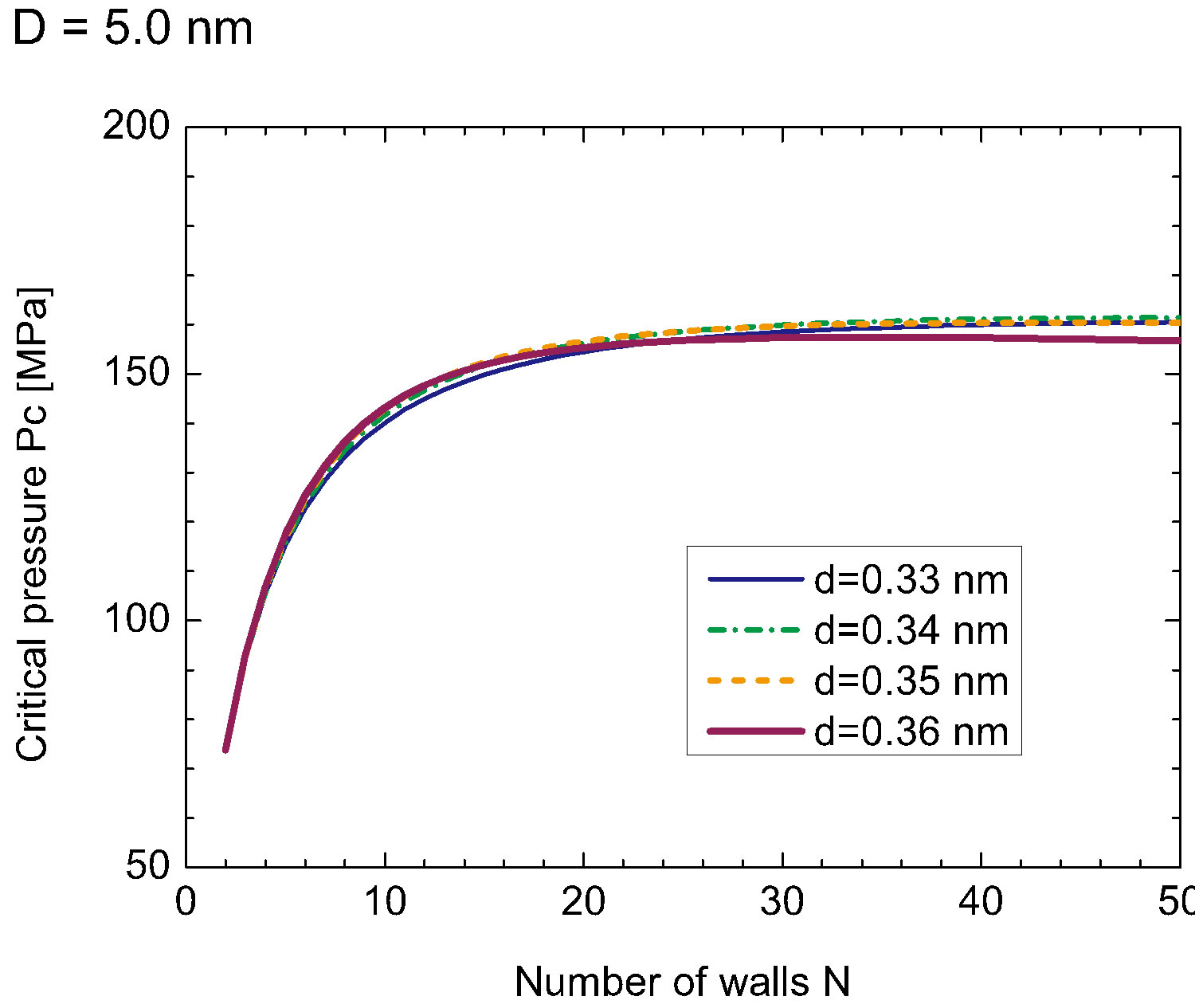 (b)
(b)
Figure 1. (Color online) Critical pressure curves showing Pc required to produce radial deformation of N-walled nanotubes with fixed D: (a) D = 3.0 nm, and (b) D = 5.0 nm.
above  for fixed
  nm and
  nm. The most striking observation is the successive transformation of the cross section with an increase in
 . We see from Figure 2(a) that the deformation mode observed just above
  jumps abruptly from
  to n = 8 at
 , which is followed by successive emergences of higher corrugation modes with larger
 . These transitions in
  originate from the two competing effects inherent in MWNTs with N = 1, that is, the relative rigidity of the inner tubes and the mechanical instability of the outer tubes. A large discrepancy in the radial stiffness of the inner and outer tubes gives rise to an uneven distribution of the deformation amplitudes of concentric tubes that interact through the vdW forces, which consequently produces an abrupt change in the observed deformation mode at some
 .
.
4.3. Hard-to-Soft Transition
Of further interest is that the critical number of tubes  separating the elliptic phase (
 ) from the corrugation phase (
 ) is identified as the
  that
that
 (a)
(a)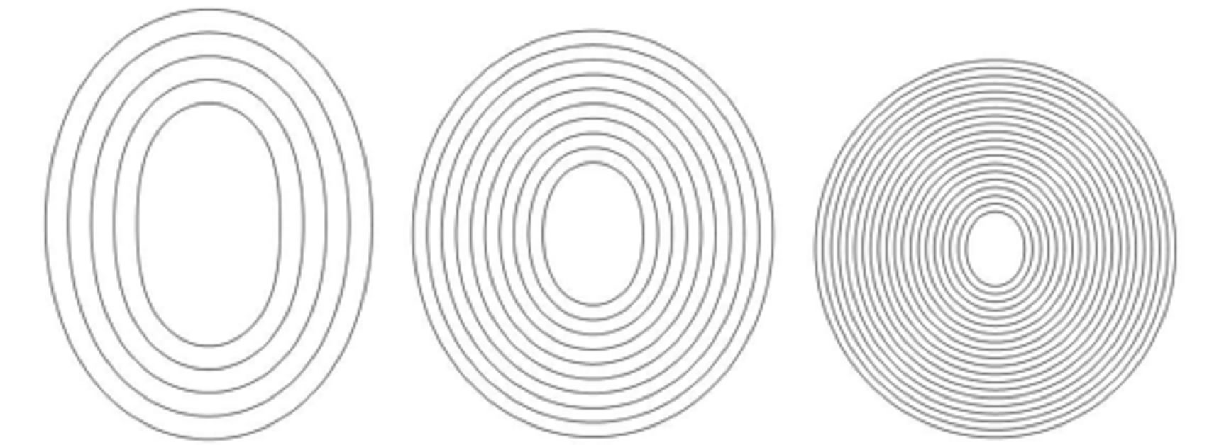 (b)
(b)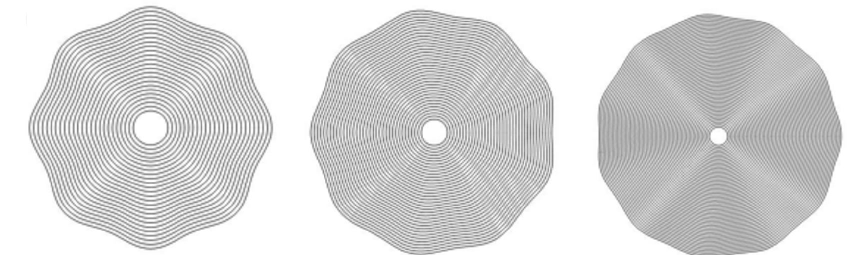 (c)
(c)
Figure 2. [Upper panel] (a) Stepwise increase in the index n of radial buckling modes. The index n indicates the circumferential wave number of the deformed cross-section. [Bottom panel] Cross-sectional views of buckled MWNTs under high hydrostatic pressure: (b)-(d) Elliptic deformation mode (n = 2) for N = 5, 10, 20; (e) Radial corrugation mode with n = 8 for N = 25; (f) n = 9 for N = 35; (g) n = 11 for N = 50.
yields a cusp in the curve of  [see Figure 1(a)]. In contrast, no singularity is observed in the curve of
  at any value of
 , which separates two neighboring corrugation phases. We emphasize that at these phase boundaries, one additional tube induces a drastic change in the cross-sectional shape of the MWNT under hydrostatic pressure.
Figure 3 explains why the singular cusp in the  curve corresponds to the hard-to-soft transition point of
 . This figure shows the N-dependence of the solutions
  for the secular equation
 . As mentioned earlier, the secular equation provides various values of
 . Each of these values is associated with a specific mode index
 . The minimum value of p gives the critical pressure
  just above which cross-sectional deformation takes place. Figure 3 depicts the N-dependence of
  for several
  values, where the innermost tube radius is fixed to be
  nm. For
 , the values of
  for
for  are less than those for
 , which implies that the elliptic mode occurs for MWNTs with
 . However, at
  (and
(and ), the minimum
  corre-