A Hybrid Algorithm to Address Ambiguities in Deformable Image Registration for Radiation Therapy ()
1. Introduction
Deformable image registration is becoming an important tool for tracking changes in a patient’s anatomy during radiotherapy [1-9]. The image-intensity method [10] and the landmark method [11] are two main categories used in radiation therapy. Landmark-based registration requires the identification of a sparse set of control-point pairs in both the source and target images. Therefore, it is usually tedious, and subject to inter-observer variations in identifying landmark points. This is especially true for three-dimensional (3D) registration requiring identification of a large number of landmark points. On the other hand, image intensity-based registration usually can be done automatically using image intensity information as the sole input parameters. However, image intensitybased registration is subject to intensity variations caused by various imaging artifacts. Because little user input is required in the intensity-based registration process, correspondence ambiguity in image intensity can be a problem in certain situations [12]. Correspondence ambiguity may lead to unrealistic deformations, a typical example of which is low intensity contrast within the prostate and bladder region, where intensity-based registration tends to produce an unsatisfactory motion field owing to the lack of image features. The landmark-based registration algorithm is less dependent of the underlying image content than intensity-based approach if a set of key feature correspondences can be reliably defined. However, automatic and accurate building a large number of feature correspondences across an image pair is generally a tough problem, and manually labeling the correspondences can be extremely labor-intensive. In addition, the validity of landmark-based registration depends on the number and distribution of control points.
To improve the robustness and accuracy of deformable image registration in certain clinical situations, we have proposed a hybrid registration approach that combines the landmark-based method, using compact-support radial basis functions (CSRBFs) [13] with the intensity-based diffusion method [2,3]. In this hybrid approach, CSRBF spline registration was used to establish correspondences over in the local region defined by a sparse set of landmarks; while the regions distant away from landmarks were registered using the image intensitybased diffusion method. We used a multi-step strategy in our implementation of CSRBFs that can handle large geometric deformations.
Though some researchers have proposed combination of image intensity and landmarks for registration [14-18], the major difference is that they applied both image intensityand landmark-based registrations to the entire image and calculated the registration by optimization of global cost function. In our proposed method, the image intensity-based registration applies to the entire image; while the landmark-based registration applies only to a local region where accurate registration results cannot be achieved using intensity-based registration alone. We also proposed a multi-step CSRBF registration method that has proven to be robust in handling large deformations and insensitive to the registration parameters used.
2. Materials and Methods
2.1. Intensity-Based Diffusion Registration
Image intensity-based registration is also called voxel similarity-based registration because the registration metric and the cost function is calculated directly using the voxel-intensity values of the two images to be registered, i.e., source S(x) image and target T(x) image [10]. The registration process involves transforming the source image to best match the target image. The sum of squared-intensity differences (SSD) between source and target images is usually used in conjunction with a smoothness constraint, which can simulate various mechanical property of the material. For example, elastic image registration simulates the linear elastic material, and fluid image registration [19-21] simulates deformations in fluid dynamics. A generic diffusion-type image registration model can be constructed using the Tikhonov regularization constraint [2,3,17]. Thirion’s [22] demons registration algorithm [8,9] can be regarded as an approximation of the diffusion registration model using isotropic filtering.
We previously implemented a variational diffusion registration [2], where the displacement vector field uk (k = x, y, z in the Cartesian coordinate system) can be determined by solving the registration equation [2,3,17].
 (1)
(1)
where a is the smooth parameter; S(xk) and T(xk) are the source and target image intensities, respectively; and  . The displacement fields are the solutions of the nonlinear partial differential equations in Equation (1), and these equations can be solved numerically using a multigrid method [2].
2.2. Landmark-Based Registration Using CSRBF Spline
CSRBF spline registration requires user intervention to establish the correspondences between the same object in both source and target images. The main steps in landmark based registration algorithm consist of identifying pairs of corresponding landmarks in images, computing the appropriate transformation parameters, and then interpolating transformation fields for positions not on the landmarks.
The properties of radial basis functions (RBFs) are well defined and have proven to be efficient for interpolation [23]. Researchers have proposed using many different RBFs for landmark-based image registration with or without compact support[13]. The main disadvantage of RBFs without compact support is that the resultant transformation acts as a global function so that a single landmark pair would affect entire image region, a typical example is thin-plate spline (TPS). The transformations generated by CSRBF are localized, and the impacts of landmarks on a certain location are inversely proportional to the distances to the landmarks. In our implementation, we selected the Wendland y function [23] as the RBF with the spatial-support parameter a for local registration:
 (2)
(2)
where
 (3)
(3)
This function is positively defined in a 3D space and has C2 continuity (second derivative continuity). An RBF is based on a scalar radius r and is symmetric around a control point. The smaller the value of a, the more local the confinement of for at the landmark control points. To handle large deformations using CSRBF spline registration, a large a value may be needed [13]. Therefore, selection of this a parameter must be a compromise between the requirement for local confinement and the existence of large deformations in certain clinical situations.
CSRBF spline registration initially identifies the corresponding coordinate locations (control points) in both source and target images. The control-point pairs are then used to determine a coordinate transformation (mapping) between two images. The set of control points in the source image can be denoted as , and the corresponding control-point set in the target image can be denoted as
 . A successful registration should map every point in
  to the corresponding
 . Transformation of the mapping function can be represented as a linear combination of the CSRBFs of the distance between two control-point sets:
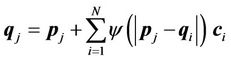 (4)
(4)
where i, j = 1, ···, N, and N is the number of control points. For a given set of control points, the transformation coefficients  are the solutions for this linear system:
 (5)
(5)
where  and
and .
.
Once the transformation coefficients  are obtained as depicted in Equation (5), the mapping between any points x other than the control points is given as follows:
 (6)
(6)
where x' is the corresponding point of x, and

is the displacement field for point x. The displacement fields generally depend on both the number and spatial distribution of control points. For a given set of controlpoint pairs, the displacement fields depend on the value of the compact support parameter a. Usually, a small a value makes the transformation more local to the control points, and the deformation of the object is relatively small. In certain clinical situations, a large a value is required to handle large deformations in a small region. When a large a value is used, the CSRBF spline transformation may influence the outer regions away from the area defined by the control points.
2.3. Multi-Step Registration Using CSRBF Spline
With large deformations, landmark-based registration may produce “cross-over” of the grid, as shown in Figure 5(c). Although a large support size can be used for regions away from the region of interest may lead to unrealistic displacement fields such as that caused by bone deformation as shown in Figure 4 (c)-(d). Joshi and Miller [24] mathematically proved the existence of diffeomorphism in a set of landmark correspondences with large deformations and derived an iterative algorithm. However, we argue that strict diffeomorphism may be overconstrained in many situations. Moreover, as a clinical solution for adaptive radiation therapy, our goal is to avoid “cross-over” in deformation with an affordable computational cost rather than solve a strict topologypreserve map. Therefore, we implemented a heuristic divide-and-conquer procedure to handle large deformation across patient anatomy while maintaining the locality of the transformation.
After selection of the control-point pairs, the distances between the corresponding points roughly represent the deformation of the subject from the source image to the target image. Using one-step registration would necessitate a large compact support parameter a for large deformation, which could violate the locality [13] of the transformation. In the present study, we implemented a multi-step CSRBF splines. We could artificially reduce the distances between the source and target control points by creating intermediate “virtual” control points between them as illustrated in Figure 1. The intermediate virtual control points are coordinates of points between source and target control points; they are not actual points identified in the images. The main reason for using these intermediate virtual control points is to reduce the distances between the source and intermediate points, making the transformation more local and topologically preserved when using Equation (4). At the end of this multi-step CSRBF registration process, the final control points are the same as the landmark points identified by the user.
The multi-step registration initially registers the source control points (real points) to the virtual control points

Figure 1. 2D representation of a multi-step CSRBF spline registration using two intermediate virtual control points (blue and yellow circles with crossed marks). The red open circles with the solid curve represent the source image, and the solid black dots are linked landmarks on the target image (dashed curve).
 , which are closest to the source control points. Next, the previous virtual control point set
  is used as the source set and registered to the next virtual control point set
 . This procedure is repeated until the final step, which registers the last set of virtual control points
  to the target control point set
 . The number of registration steps is n+1. In each step of the registration process, the same compact support parameter value a is used. The transformation coefficients
  are obtained for each step by repeatedly solving Equation (5), and these coefficients are used sequentially to calculate the displacement fields of every point using Equation (6) in the region of interest. The final displacement field between the source and target images is the cumulative displacement field obtained in the multiple steps.
2.4. The Hybrid Registration Algorithm
The image intensity-based deformable registration algorithm [2,9] works well for many clinical applications when the image quality is good and source and target images are relatively similar. The hybrid registration algorithm is designed for situations when the image quality and / or source and target similarity are inadequate for successful registration using the image intensity-based algorithm alone. Therefore, prior to the use of the hybrid registration, we first registered the image pair using intensity-based diffusion registration algorithm. We used the hybrid registration only when the diffusion registration could not produce satisfactory results.
As illustrated in the flowchart in Figure 2, the hybrid registration method includes four essential steps: 1) registering the entire region of interest using image intensity-based diffusion registration, 2) manually identifying control-point pairs in regions in which the previous registration results were considered inadequate, 3) using the multi-step CSRBF spline registration algorithm to register the local region of the image according to the predefined control-point pairs, and 4) combining the displacement fields from multi-step CSRBF spline registration with that those obtained from the diffusion registration.

Figure 2. Diagram of the proposed hybrid deformable image registration approach.
The combination of two displacement fields should satisfy the smooth constraints for the two registration methods, and the local registration should not affect global registration of the entire region. In our implementation, we first used a spline function to connect all of the landmark points to calculate a closed 3D volume. We marked the interior of this 3D volume as the “in-field” volume, where the displacement field was determined solely using the CSRBF spline registration method. We then expanded the 3D surface of this in-field volume to create a “transition zone” with the width of the expansion equal to the compact support parameter a. Within the transition zone, the displacement field  was determined according to the weighted average of both of the displacement fields calculated using the intensity-based method
  and the landmark-based method
  at each position:
 (7)
(7)
where the weighting function  can be determined using a linear function of Euclidean distance transformation
  [25,26] between the point of interest x and the 3D surface of the in-field volume:
 (8)
(8)
where the compact support parameter a normalizes the weighting function to a value within [0,1]. This is illustrated in the two-dimensional (2D) diagram in Figure 3. This implementation allows for CSRBF spline registration in the local region specified by the control points, whereas the image intensity-based diffusion registration controls the region away from the control points with a smooth transition in the transition zone.

Figure 3. A 2D diagram showing the combination of landmark-based and image intensity-based registration. The peripheral landmark points form an in-field area (shaded) in which the displacement field was determined using the landmark-based registration method only. A transition zone is identified by expanding the in-field area using the registration parameter a. In the transition zone, the displacement field is computed based on the weighted average of the displacement fields with both methods. In the “out-field” area, the displacement field was determined solely using the intensity-based registration method.
2.5. Patient Data
Computed tomography (CT) images for four patients with prostate cancer, two patients with lung cancer, and one patient with head and neck cancer were used to test the accuracy and efficiency of the hybrid deformable image registration method. For the prostate cancer patients, daily (target) CT images were acquired using a CT-on-rails system (EXaCT; Varian Medical Systems, Palo Alto, CA). For the lung cancer patients, four-dimensional (4D) CT images were used to test the registration of tumor sliding along chest wall. The 4D CT data were reconstructed using CT scans acquired synchronously with the respiratory signals representing 3D CT data sets at various breathing phases (total, 10 phases). In 4D CT images, the 0% phase CT images (denoted by T0) and 50% phase CT images (denoted by T5), corresponding to the end of inspiration and expiration scans, respectively, and the largest range of tumor motion owing to respiration appears in the CT images in these two phases.
2.6. Validation Method
We used the results of the deformable image registration to determine whether this transformation can correctly auto-delineate the daily target volume. In this procedure the manually drawn contours in the source CT image were transformed to the contour in target CT image using the displacement field calculated from deformable image registration. The deformed contours in the target image automatically segmented the anatomic structures in the target image. Precise registration led to the deformed contours correctly fitting the corresponding structures in the target image. Therefore, the deformed contours facilitated evaluation of the image registration algorithm. The deformable image registration methods were implemented using the C++ programming language. All tests were run on an Intel Pentium IV (2.8 GHz)-equipped personal computer.
3. Results
3.1. Single-step vs Multi-Step CSRBF Spline Registration
In the multi-step CSRBF registration algorithm, the number of steps is specified by the user and depends mainly on the distances between source and target control points. Our experience showed that a four-step procedure is reasonable for challenging cases with very large deformations.
Figure 4 shows the differences in one-, two-, threeand four-step registration using an artificial cuboid in the prostate cancer CT images. We identified 18 controlpoint pairs on the edges of the rectangle denoting the cuboid in one particular slice. This figure demonstrates