Discrete Event Net Based Modeling and Control System Design for Real-Time Concurrent Control of Multiple Robot Systems ()
1. Introduction
Recently, based on the rapid development of the microprocessor technology, the factory automation systems have been continuing to become more and more largescaled, complicated, and integrated. The two flows of control and data must be organized in the system, but to achieve it, system concept, system architecture, and system design method are not established sufficiently. Some techniques derived from Petri nets have been successfully introduced as an effective tool for representing control specifications including concurrent processes, which are characteristic of complex systems, analyzing system properties and designing control systems [1]. Especially, Petri nets are used to indicate the flow of control, and by decomposing the net, the concept of upper and lower control levels is clarified. The coordinator is defined as the agent which consistently executes the flow of control in the upper control level bringing about cooperation among the local machine controllers in the lower control level. The microprocessors seem to be the most suitable to realize the coordinator. They can be used to realize the coordinators corresponding to decomposed nets, besides the coordinator in the upper control level, using software directly on the same hardware.
The representation scheme of concurrent robotic activities as a decision logic structure is essential to control multiple robot systems that may be considered the most significant development in robotics fields [2-4]. The author presents a net based methodology for synthesizing complicated control software hierarchically for large and complex robotic systems, especially multiple robot systems. An algorithm is proposed for coordination of machine controllers so that robots can synchronize activities and avoid harmful conflicts. By the proposed method, highly reliable and efficient development of complicated real-time concurrent control algorithms for multiple robotic processes can be achieved.
2. Modeling of Discrete Event Robot Systems with Petri Nets
A Petri net comprises two types of nodes, places representing conditions (or states) and transitions representing events, which are interconnected by directed arcs [5]. Tokens, which reside at the places, are used to indicate the instantiation of a state. The current state of a net is represented by the distribution of tokens, or the marking, in the net. In a Petri net, the places, transitions and tokens are represented by the circles, bars and dots respectively. There are many forms of Petri net. The type considered here is the condition-event net in which each place can contain not more than one token. This allows a one-toone semantic correspondence between places and conditions.
Formally, a net is a bipartite graph represented by the 4-tuple 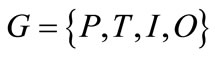 such that:
 is a finite set of places;
 is a finite set of transitions;
 is the input function that maps transitions to bags of places;
 is the output function that maps transitions to bags of places.
Thus the axioms of nets are as follows:
1) A transition is enabled, if and only if, each of its input places has one token and each of its output places has no token;
2) When an enabled transition fires, the marking is changed to the new one, where each of its input places has no token and each of output places has one token.
A transition without any input place is called a source transition, and one without any output place is called a sink transition. A source transition is unconditionally enabled, and the firing of a sink transition consumes a token in each input place but does not produce any. According to these axioms, the number of tokens in each place never exceeds one, thus, the net is essentially 1- bounded and said to be a safe graph.
In a net, a place represents a condition or state of a process or resource. A transition corresponds to an event or action. The input places of the transition define the conditions to the executions of the action. The output places define the results of the action. A token is placed in a place to indicate that the condition corresponding to the place is holding.
Conceptually, robotic processes are represented as sequential constructs or state machines, where each transition has exactly one incoming arc and exactly one outgoing arc. The structure of a place having two or more input or output transitions is referred to as a conflict, decision, or choice, depending on applications. State machines allow the representation of decisions, but not the synchronization of parallel activities.
The condition-event net is a subclass of Petri nets, so it can be represented by the ordinary Petri net [6]. Figures 1(a) and (b) illustrate a simple net and its equivalent net represented by the ordinary Petri net, which is achieved by addition of a place with the inversion of the existence of token and the directions of its input and output arcs, for each place of the net. The enabling rule for the ordinary Petri net, where all of its arc weights are 1, is that a transition is enabled, if and only if, each of its input places has more than one token.
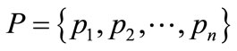
If there is no conflict place in a net, the net can be transformed to one with no loop, as shown in Figure 2. If there is a loop with no conflict place in a net, then the
 (a) (b)
Figure 1. (a) A simple net and (b) its equivalent Petri net.
 (a) (b)
Figure 2. (a) A net with no conflict place and (b) its equivalent net with no loop.
number of tokens in the loop is not changed.
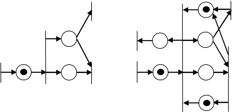
In case that there is initially no token in a net, if there is one token in a direct path between two transitions, then there is one token in one place in each of other paths between the transitions. Further, addition of a direct path in a path between the transitions does mot change the enabling conditions of the transitions in the net, as shown in Figures 3(a) and (b). Generally, if there are several concurrent paths in two transitions and if there is initially no token in the net, the maximum number of tokens in each path is the least number of places in the paths.
The condition-event net can be easily extended to adopt the following elements as input and output interfaces which connect the net to its environment: gate arcs and output arcs. A gate arc connects a transition with a status signal source, and depending on the signal, it either permits or inhibits the occurrence of the event. An output arc connects a place with an external machine and sends a command signal to the machine. These interfaces are represented by transitions which represent the communication activities of the net with its environment.
The places are connected via transitions, each having a boolean condition or gate condition. This condition is tested while the transition is enabled, i.e., when the preceding place is active. If the condition is true, the succeeding place becomes active, and the preceding place becomes inactive. Using gate arcs, an enabled transition fires when 1) it does not have any internal permissive arc signaling 0 nor any internal inhibitive arc signaling 1 and 2) it does not have any external permissive arc signaling 0 nor any external inhibitive arc signaling 1. Figure 4 illustrates place and gate variables involved in transition
 (a) (b)
Figure 3. (a) A net with direct path and (b) addition of dummy direct path.

Figure 4. Place and gate variables involved in transition firing.
firing. The firing condition is expressed formally using logical variables as follows.
The logical variable  is set to 1 if a token is entered into the place, and reset to 0 if a token is removed from the place. The logical variable
  is set to 1 if the gate condition is 1 (i.e. permissive signal on), and reset to 0 if it is 0 (i.e. signal off). The logical variable
  is set to 1 if the transition is fired, and reset to 0 if it is not fired. Hence, from the above firing rules, the firing condition of transition
  can be written as
 (1)
(1)
where  denotes the logical product operation, and
 : set of input places of transition
 .
.
 : set of output places of transition
 .
.
The marking change of input and output places of transition  can be described as follows:
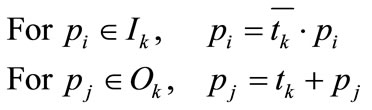 (2)
(2)
From Equation (1), by the inversion of the existence of token and the directions of its input and output arcs of a place, the enabling condition of every transition is not changed. Using the above procedure, if a net has no conflict place, the net can be transformed into a net with no loop.
The dynamic behavior of the system represented by a net model is simulated using the enabling and firing rules. One cycle of the simulation comprises the following two steps.
1) Calculate the logical variables of all transitions  using Equation (1).
2) Calculate the logical variables of all places 
 using Equation (2).
For efficient simulation combined with real-time control of a robotic system, the following steps are executed only when some gate condition is changed.
1) Calculate the logical variable of the transition associated with the new gate condition using Equation (1).
2) If the transition is fired, calculate the logical variables of its input and output places using Equation (2).
3) Then the marking is changed and a new command is sent to the corresponding machine.
Figure 5 shows the net representation of real-time control of a robotic unit action. When a token is placed in a place which represents an action, the net based controller initiates the execution of the action attached to the fired transition by sending the “start” signal through the output arc to the robot. Then the robot interprets the request and sends an acknowledgement to the controller. When the action is completed, the robot sends an “end” report to the controller.
Figure 6 shows a net with parallel processes and its decomposition into two subnets using permissive and inhibitive gate arcs. Shared transitions are decomposed and assigned to the subnets, which exchange the signals